6.3
Measurement of Line Impedance and Prospective Short Circuit Current
Line Impedance on single-phase system is the impedance measured
between phase and neutral terminals.
Measurement principle used inside the instrument is exactly the same as at
Fault Loop Impedance measurement, but the measurement is carried out
between L and N terminals.
Breaking current capacity of installed over-current protection devices should
be higher than Prospective Short-Circuit current,
otherwise it is necessary
to change the rated current of involved over-current protection device.
Practical example of line impedance test and prospective short-circuit
current test:
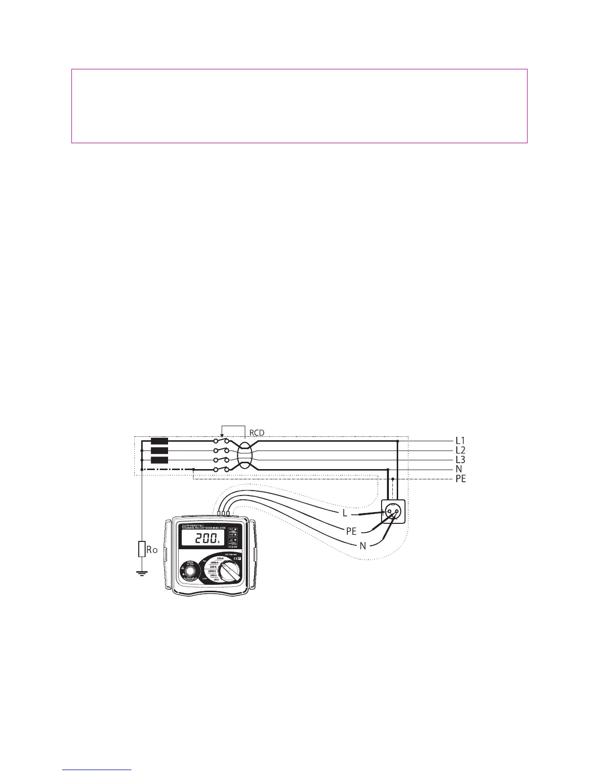
The figure below shows in marked line the Line impedance phase to neutral
for TN system.
Fig.11
#
WARNING
(OLD-TT system only)
●
DO NOT PRESS
the "Test button" if the display reads a value of
220V!
 Loading...