3.2 Test Lead
The instrument is supplied with Model 7125 lead at socket outlets and Model
7121B distribution board lead.
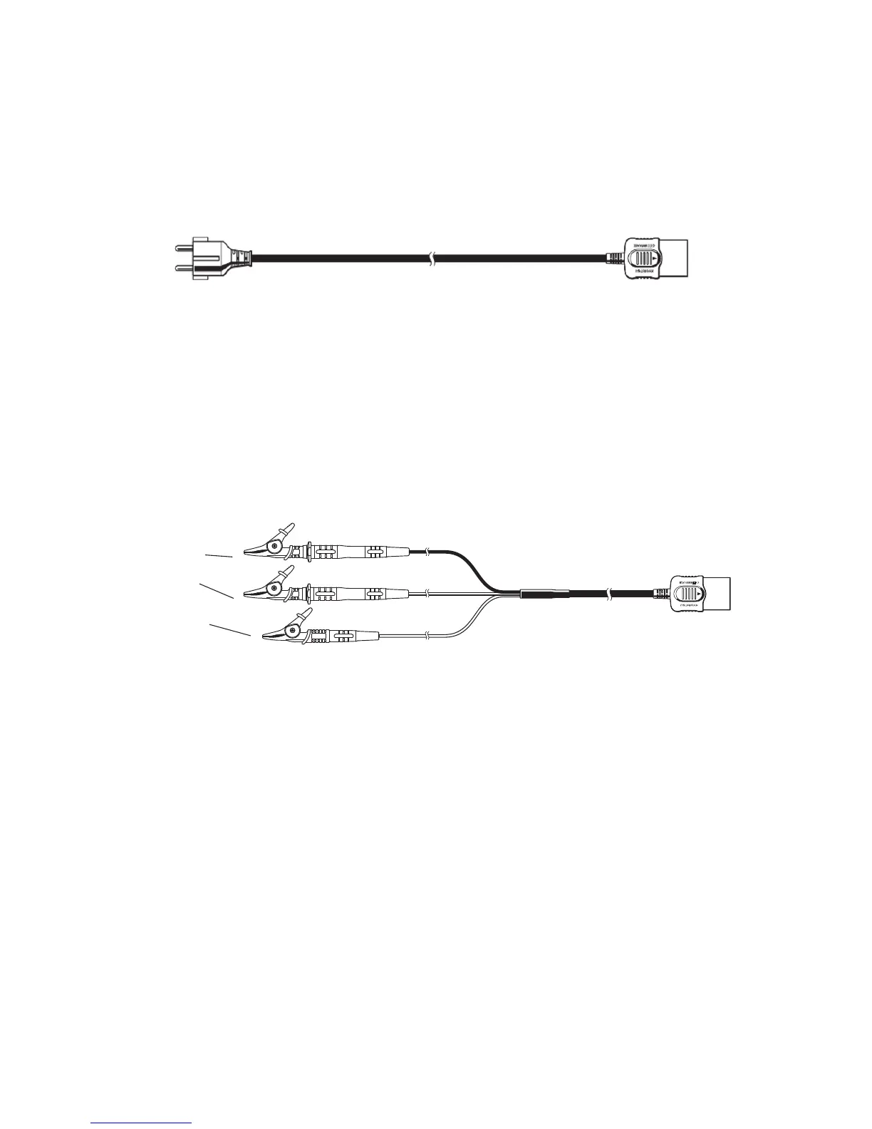
(1) Model 7125
Mains lead mentioned in this instruction manual is Model 7125(EU)
European SCHUKO plug, however, there are some other types for the
areas, and the shipping is made along with the suitable plug-shaped
cable according to the areas of the globe as follows;
Model 7123 (AU) for Australian plug
Model 7124 (UK) for British plug (13A)
Model 7126 (SA) for South African plug
(2) Model 7121B
Black-Neutral
Red-Phase
Green-Earth
Fig.4
The loop impedance of this instrument is adjusted to show the true value by
using the attached mains lead (either of Models 7123 through 7126) prior
to the shipment.
However, when the attached test lead for distribution board Model 7121B
is used, the total internal resistance shows approx. 0.1Ω bigger than those
of other mains lead due to the internal fuse resistance. Therefore, when
measurement is taken by using the Model 7121B, the measured value
between PHASE-EARTH shows approx. 0.1Ω bigger than the true value.
PHASE make sure that 0.1Ω subtracted from the measured value leaves
the true value in case of using the test lead of this distribution board.
As for the PSC range, use the following equation and divide supply voltage
by loop impedance, therefore, the measured value shows smaller than the
true value contrary to the case of the case of loop impedance range.
● PSC(A) = Supply Voltage(V) / Loop Impedance(Ω)