Do you have a question about the KYORITSU KEW 6010B and is the answer not in the manual?
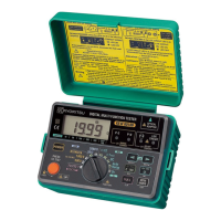
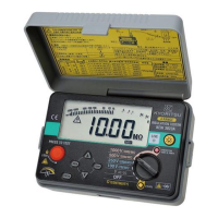
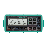
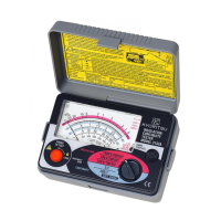
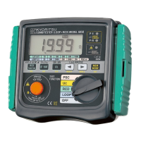
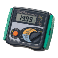
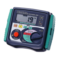
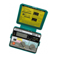
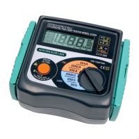
Describes the various controls, LEDs, and display elements of the instrument.
Details the uncertainty of measurements for different functions.
Specifies RCD instrumental uncertainty, earth electrode resistance, and operating conditions.
Describes LED indications for live circuits, polarity, overload protection, and voltage display.
Step-by-step guide for performing continuity tests.
Explains insulation resistance components: capacitive, conduction, and surface leakage currents.
Warns about potential damage to electronic equipment during insulation testing.
Outlines checks and preparations required before performing insulation resistance measurements.
Describes how to measure supply voltage when performing loop impedance tests.
Explains the concept of earth fault loop impedance and its importance.
Details the instrument's protection against overheating during prolonged testing.
Provides instructions and precautions for conducting loop impedance tests.
Explains the importance of RCD testing for ensuring safety against electric shock.
Describes how the RCD test measures residual current and trip time.
Defines Uc (voltage across the fault path to earth) and its significance.
Details the procedure for performing Uc voltage measurements.
Covers various RCD test types like "NO TRIP", "TRIP", "FAST TRIP", DC sensitive, and Auto Ramp.
Step-by-step instructions for saving measurement results in the instrument's memory.
Explains how to retrieve previously saved measurement data from the instrument.
Provides instructions for deleting stored measurement results from the instrument's memory.
Guides users on transferring stored data to a PC using an optical adapter and software.
Lists the PC and software requirements for data transfer.
Instructions for replacing the instrument's batteries, including precautions.
Details the process for replacing the fuse, including its location and testing.
| Model | KEW 6010B |
|---|---|
| Category | Test Equipment |
| AC Voltage Measurement | 0 to 600V |
| DC Voltage Measurement | 0 to 600V |
| Earth Resistance Measurement Range | 0 to 2000Ω |
| Earth Voltage Measurement Range | 0 to 600V |
| Earth Voltage Accuracy | ±(3%+5dgt) |
| Display | LCD |
| Power Supply | 6 x 1.5V AA batteries |
| Safety Standards | IEC61010-1 |