Do you have a question about the KYORITSU 4118A and is the answer not in the manual?
Details conditions and actions likely to cause serious or fatal injury.
Details conditions and actions that can cause serious injury or instrument damage.
Details conditions and actions that can cause minor injury or instrument damage.
Explains IEC 61010 measurement categories (O to CAT IV) for electrical environments.
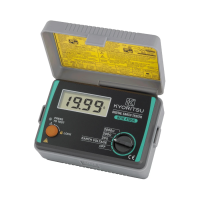
Step-by-step instructions for detaching the protective cover from the main body.
Instructions for attaching the cover to the back side of the main body during measurement.
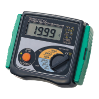
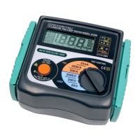
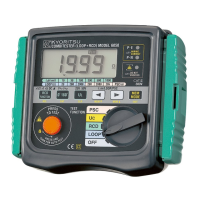
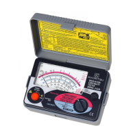
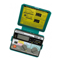
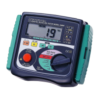
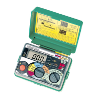
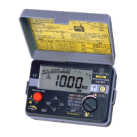
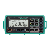
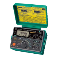
Identifies and labels the main components and controls of the instrument.
Details the different types of test leads supplied with the instrument.
Covers test ranges, applied standards, and specific model features.
Details loop impedance and prospective short-circuit current measurement ranges and accuracies.
Outlines instrument dimensions, weight, operating/storage conditions, and safety symbols.
Essential pre-test steps including lead connection and wiring validation using LEDs.
Detailed steps for performing loop impedance measurements accurately.
Step-by-step guide for measuring prospective short circuit current.
Explains the principles behind measuring fault loop impedance and prospective fault current.
Details how to measure loop impedance in an OLD-TT system with specific voltage conditions.
Explains measuring line impedance and prospective short circuit current for single-phase systems.
Instructions for returning the tester for service if it fails to operate correctly.
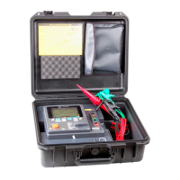
Describes how to assemble and attach the carrying strap and case for the instrument.
| Display | LCD |
|---|---|
| Data Hold | Yes |
| Test Voltage | 250V, 500V, 1000V |
| Measuring Frequency | 50Hz/60Hz |
| Power Supply | 8 x AA batteries |