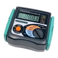
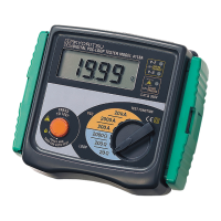
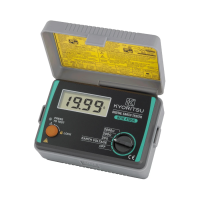
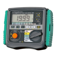
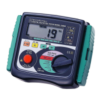
This document describes the KYORITSU DIGITAL PSC-LOOP TESTER, Models 4116A, 4118A, and 4120A, an instrument designed for measuring prospective short circuit (PSC) current and loop impedance in electrical installations.
Function Description
The primary function of this instrument is to measure fault loop impedance and prospective short circuit current (PSC) in single-phase AC systems. It is specifically designed for use in 230V +10% -15% AC phase-to-earth systems or OLD-TT systems phase-to-neutral. The tester helps ensure the automatic disconnection of supply by protection devices within prescribed time intervals in the event of a fault.
For TT systems, the fault loop impedance is calculated as the sum of the power transformer's secondary impedance, phase conductor resistance from the transformer to the fault location, protection conductor resistance from the fault location to the local earth system, the resistance of the local earth system (R), and the resistance of the power transformer's earth system (Ro). The instrument assists in verifying that the condition RA ≤ 50/Ia is fulfilled for each circuit, where RA is the sum of the resistances of the local earth system R and the protection conductor, and Ia is the current causing automatic disconnection within 5 seconds.
For TN systems, the fault loop impedance is the sum of the power transformer's secondary impedance, phase conductor resistance from the transformer to the fault location, and protection conductor resistance from the fault location to the power transformer. The instrument helps verify that the condition Zs ≤ Uo/Ia is fulfilled for each circuit, where Zs is the fault loop impedance, Uo is the nominal voltage between phase to earth, and Ia is the current causing automatic disconnection within the time stated in relevant tables.
The instrument also measures line impedance and prospective short circuit current between phase and neutral terminals in single-phase systems. This measurement principle is identical to fault loop impedance measurement but applied to L-N terminals. It helps determine if the breaking current capacity of installed over-current protection devices is sufficient.
Usage Features
The tester is designed for ease of use and safety. It is not battery-operated, drawing its power directly from the system under test.
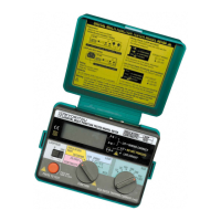
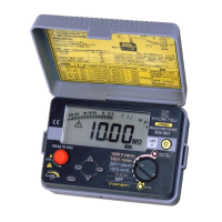
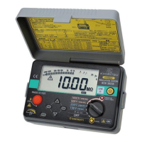
- Wiring Check: Three LEDs (P-E, P-N, and Reverse) indicate the correctness of the circuit wiring. Green LEDs for P-E and P-N indicate correct polarity, while a Red LED indicates reversed L/N terminals. This ensures safe and accurate testing.
- Voltage Measurement: Upon connection, the instrument displays the phase-neutral voltage, updated every second, allowing users to verify normal voltage conditions before proceeding with tests.
- Loop Impedance Measurement: Users can select between 200 Ω or 2000 Ω ranges. For optimal accuracy, testing on the lowest possible range is recommended. An "OL" symbol appears if the reading exceeds the selected range.
- PSC Measurement (Models 4118A and 4120A): The instrument can be set to the 20kA range to directly display the prospective short circuit current on the LCD. The reading remains for 3 seconds before reverting to AC voltage display, accompanied by an audible beep.
- D-LOK Circuit (Model 4120A): This unique feature avoids the need to bypass most Residual Current Devices (RCDs) during testing, simplifying the procedure. However, it may not bypass all RCDs, especially high-sensitivity ones (10mA or less), which might still trip.
- 15mA Loop Measurement: A 2000 Ω range measurement is performed with a low test current of 15mA, preventing the tripping of RCDs, even those with a nominal differential current of 30mA.
- Over Temperature Protection: The instrument detects overheating of its internal resistor, displaying a warning symbol (✔) and automatically halting further measurements to prevent damage.
- Overload Protection: Measurement is halted if the voltage between VL-PE exceeds 260V, displaying "VL-PE Hi" to prevent damage to the device.
- Manual and Autotest Mode:
- Manual: Pressing and releasing the "Press to Test" button displays the result for 3 seconds before reverting to AC voltage.
- Autotest: Turning the "Press to Test" button clockwise locks it down. When using the distribution board lead M-7121, tests can be conducted by simply disconnecting and reconnecting the red phase prod, eliminating the need to physically press the button ("hands free").
- LCD Display: A 3 1/2 digit liquid crystal display shows measurements in Ω, A, kA, or V, with a decimal point.
- OLD-TT System Measurement: When connected to an OLD-TT system (220V phase-to-phase, 127V phase-to-earth, neutral conductor not typically used), all three wiring check LEDs should illuminate, and the display should read 127V before testing.
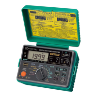
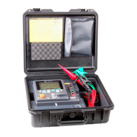
- Protective Cover: Models 4116A, 4118A, and 4120A come with a dedicated cover to protect against impact, dirt, and to safeguard the operation part, LCD, and connector socket. The cover can be detached and placed on the back of the main body during use.
- Test Leads: The instrument is supplied with Model 7125 lead for socket outlets and Model 7121 distribution board lead (standard for M-4118A and 4120A, optional for M-4116A). Only original test leads should be used.
- Strap Belt Assembly: The instrument can be hung around the neck using the strap belt, leaving both hands free for testing.
Maintenance Features
- Cleaning: The instrument should be cleaned with a damp cloth and detergent. Abrasives or solvents should not be used.
- Troubleshooting: In case of malfunction, the instrument should be returned to the distributor for inspection and repair, providing detailed information about the fault.
- Safety Warnings: Users are warned not to open the instrument case due to dangerous voltages. If the overheat symbol appears, the instrument should be disconnected from the mains and allowed to cool. Any abnormal conditions (faulty display, unexpected readings, broken case, cracked test leads) necessitate returning the tester for repair. The instrument should never be used if it or the user's hand is wet.