―
9
―
(3)VoltageMeasurement
Whenthe instrument isfirst connectedto thesystem, itwill displaythe
phase-neutralvoltagewhichisupdatedevery1s.Thismodeiscancelled
wheneverthe test button ispressed. If this voltageis not normal or as
expected,DONOTPROCEED.
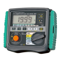
5.2MeasurementoftheLoopImpedance
(1)Settheinstrumenttothe200Ω or2000Ω range.
Ifthe instrument is set to the 20Ω rangeslight sparking may occur
whentesting withthe distributionboard lead althoughthe unithas
beendesignedtominimizethis.
(2)Connecttheleadtotheinstrument.
(3)Plugthemouldedmainsplugtothesocketbeingtested.
(4)Checkthe LED's arelit as indicatedin section 5.1. Ifnot DO NOT
PROCEED-checkwiring.
(5)Notethemainsvoltageifrequired.
(6)Pressthe"PresstoTest"button.Thevalueofloopimpedancewillbe
displayedwiththeappropriateunits.Ableepwillsoundoncompletion
ofthetest.
Forbestresultsalwaystestonthelowestpossiblerange.
Forexample, a loop impedance measured on the 200Ω rangemay
giveanindicationof0.3Ω whereasonthe20Ω rangeitmayread0.28
Ω.Intheeventofthereadingbeinginexcessoftherange(e.g.more
than20Ω onthe20Ω range)theappropriateover-rangesymbol"OL"
willappearonthedisplay.
Noharmwillbedonetotheinstrumentbyselectingtoolowarange.
WARNING
● IftheabovesequenceisNOTdisplayedortheREDLEDisonfor
anyreason , DO NOT PROCEED AS THEREIS INCORRECT
WIRING.Thecauseofthefaultmustbeinvestigatedandrectified.
WARNING
● Thisinstrumentisintendedonlyforuseinsinglephaseoperation
at230V+10% -15%AC phasetoearth orfor useinOLD-TT
systemphasetoneutral.