Do you have a question about the KYORITSU 6010A and is the answer not in the manual?
Detects overheating and halts measurements, displaying a warning symbol.
Allows selection of test half-cycle for improved RCD and loop testing accuracy.
Automatically freezes the displayed reading for 5 seconds after measurement.
The instrument automatically switches off after approximately 1 minute of inactivity.
Aborts RCD measurements if N-E voltage exceeds 50V, indicated by 'VNE Hi'.
Refers to an optional test lead for distribution board or lighting circuit testing.
Measurement specifications for continuity tests according to IEC61557-4 standard.
Measurement specifications for insulation resistance tests as per IEC61557-2.
Measurement specifications for loop impedance tests following IEC61557-3.
Measurement specifications for RCD testing according to IEC61557-6.
Specifications related to the voltage measurement capability of the tester.
Specifies the physical size of the instrument, including height, width, and depth.
Indicates the total weight of the tester, including the batteries.
Lists the standard environmental conditions under which specifications are valid.
Identifies the type and number of batteries required for operation.
Describes the indicator for low battery voltage and its threshold.
Estimates the number of tests possible with a fresh set of batteries.
Defines the acceptable range of temperature and humidity for operation.
Defines the acceptable range of temperature and humidity for storage.
Explains the function of LEDs indicating a live circuit during tests.
Describes LEDs that confirm correct wiring polarity.
Details the automatic freezing of readings in loop and RCD test modes.
Describes the characteristics of the instrument's digital display.
Details protection mechanisms against overloads for specific test circuits.
Explains how mains voltage is displayed and indicated on the tester.
Defines safety and operational symbols found on the tester.
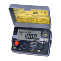
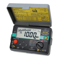
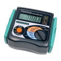
Diagram showing the layout of controls and indicators on the instrument.
Method for measuring and compensating for the resistance of test leads.
Step-by-step instructions for executing continuity tests on circuits.
Explains insulation resistance concepts and leakage current components.
Details the behavior of capacitive current during insulation testing.
Explains the conduction current component of leakage in insulation.
Describes surface leakage current and its dependence on surface conditions.
Defines total leakage current as the sum of component leakage currents.
Warns about potential damage to electronic devices and advises disconnection.
Lists essential checks before performing insulation resistance measurements.
Step-by-step procedure for measuring insulation resistance.
Describes how the tester displays mains voltage during loop testing.
Explains the concept of earth fault loop impedance and its importance.
Details the instrument's protection against overheating during tests.
Detailed procedure for conducting loop impedance tests on circuits.
Instructions for performing loop impedance tests on 3-phase systems.
Explains the necessity of RCD testing for user safety.
Details how the RCD test measures tripping time and residual current.
Step-by-step guide for performing standard RCD trip tests.
Specific procedure for testing fast-acting RCDs rated at 30mA or less.
Procedure for testing RCDs with built-in time delays for discrimination.
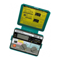
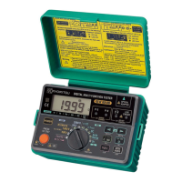
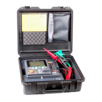
The KYORITSU MODEL 6010A is a multi-function tester designed for electrical installations, combining five essential testing functions into a single, robust instrument. This device is built to Safety Standard IEC 61010-1/EN 61010-1 CAT III (300V) and features a dust-proof construction conforming to IP50, IEC529, ensuring reliability in various working environments.
The MODEL 6010A offers the following primary functions:
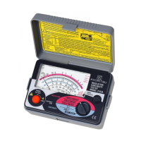
Continuity Tester: This function measures the resistance of wiring systems. It provides a short circuit current of 200mA, as required by IEC 61557-4/EN 61557-4 1997. The instrument is designed to exclude the resistance of the test leads from the measurement, requiring users to first measure and subtract lead resistance for accurate results. It features a live circuit warning LED and a beeper that warns when the test current exceeds 200mA during continuity measurement. This mode is intended for use only on de-energised circuits.
Insulation Resistance Tester: This mode measures the insulation resistance between live conductors and between conductors and earth metal. It applies a direct voltage of 500V DC and provides a rated current of 1mA, as required by IEC 61557-2/EN 61557-2 1997. The instrument automatically discharges stored electric charges in capacitive circuits after testing, enhancing safety. Similar to continuity testing, this function must only be used on de-energised circuits. The live circuit warning LED also operates in this mode.
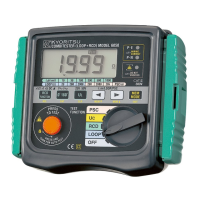
Loop Impedance Tester: This function measures the earth fault loop impedance, which is crucial for ensuring that protective devices (fuses or circuit breakers) operate quickly enough in the event of a fault. The instrument displays the supply voltage when connected to the mains and includes three LEDs to indicate correct wiring. To prevent unwanted tripping of Residual Current Devices (RCDs) during loop testing, RCDs must be temporarily replaced with a suitably rated Miniature Circuit Breaker (MCB) unit. The test can be selected from either the positive (0°) or negative (180°) half-cycle of voltage to prevent tripping of some polarised RCDs.
RCD Tester: This mode tests the operational time of Residual Current Devices (RCDs) to ensure they trip quickly enough to prevent serious danger from electric shock. The tester provides a carefully preset residual current value, depending on its setting, and measures the time lapse between current application and RCD operation. It supports various RCD tripping currents (10/30/100/300/500mA) and includes "no trip" tests (X1/2) to confirm the RCD is operating within specification without being overly sensitive. It also supports testing of time-delayed RCDs and fast trip tests for RCDs rated at 30mA or less.
Mains Voltage Warning: When operating in loop impedance and RCD modes, the instrument provides a mains voltage warning. The LCD displays the voltage, and three LEDs indicate if the circuit wiring is correct.
The MODEL 6010A is designed for ease of use and safety:
Live Circuit Warning: A color-coded LED illuminates if an alternating voltage of 20V AC or more is detected in the circuit under test before continuity or insulation resistance tests. This also applies if DC voltage is detected across the measuring terminal. This feature serves as a critical safety reminder.
Wiring Check LEDs: In loop impedance and RCD test functions, P-E and P-N LEDs illuminate to confirm correct wiring of the circuit under test. A separate LED indicates reversed P and N connections.
Automatic Over-Temperature Cut-out: The instrument detects overheating of internal resistors and the current control MOS FET during loop and RCD tests. If overheating occurs, a warning symbol (1) appears on the display, and further measurements are automatically halted until the instrument cools down.
Auto Data Hold: After a loop impedance or RCD test is complete, the displayed reading is automatically frozen for 5 seconds, allowing the user to record the measurement easily.
Auto Power Off: To conserve battery life, the instrument automatically switches off after approximately 1 minute of inactivity.
V-NE Monitoring Circuit: In RCD ranges, the instrument automatically aborts measurement if the N-E voltage rises to 50V or greater, displaying "VNE Hi".
Phase Angle Selector: For loop and RCD tests, the user can select between positive (0°) or negative (180°) half-cycles of voltage. This helps prevent unwanted tripping of polarised RCDs during loop testing and can provide more accurate RCD test readings.
Test Button and Function Switch: The test button initiates measurements. The function switch allows selection of the desired test mode. A safety mechanism prevents rotating the function dial while the test button is depressed or in lock-down position; doing so will halt the test, requiring a reset by releasing and re-pressing the button.
Sliding Shutter: A safety device on the back of the instrument ensures that leads for continuity and insulation resistance testing cannot be connected simultaneously with leads for loop and RCD testing. This prevents incorrect connections and enhances user safety.
LCD Display: A 3 1/2 digit liquid crystal display shows measurements with decimal points and units (Ω, MΩ, V, ms). It also displays "Lo" for mains voltages below 100V and "Hi" for voltages above 260V, in which cases testing cannot be performed.
Accessories: The instrument comes with a KAMP10 lead for loop/RCD testing at socket outlets and a MODEL7122B lead for insulation and continuity testing. Optional accessories include an OMA DIEC distribution board or lighting circuit test lead for LOOP/RCD testing.
The MODEL 6010A is designed with user-friendly maintenance in mind:
Battery Replacement: The instrument is powered by eight R6 or LR6 batteries. A low battery warning symbol ("") appears on the display when the battery voltage drops below 8V, indicating that replacement is needed. Battery replacement is a simple process involving removing the battery cover and inserting new batteries, observing correct polarity.
Fuse Replacement: The continuity test circuit is protected by a 0.5A 600V fast-acting (HRC) ceramic fuse, located in the battery compartment, where a spare fuse is also stored. If the continuity test mode fails, users can easily check and replace this fuse. For failures in loop impedance or RCD modes, which involve protective fuses on the printed circuit board, the instrument should be returned to a distributor for service, as these fuses are not user-replaceable.
Cleaning: The instrument can be cleaned with a damp cloth and detergent. Abrasives or solvents should not be used.
Servicing: In case of operational failure, users are advised to check test leads, the continuity mode fuse, and battery condition before returning the instrument for service. Providing a detailed description of the fault helps expedite the servicing process.
The KYORITSU MODEL 6010A is a comprehensive and safe tool for electrical testing, designed to provide accurate measurements while prioritising user safety and ease of maintenance.
| Measurement Range (Insulation Resistance) | 0.01 MΩ to 2000 MΩ |
|---|---|
| Insulation Resistance | 0.01 MΩ to 2000 MΩ |
| Type | Insulation Tester |
| Test Voltage | 250V, 500V, 1000V |
| Display | LCD |
| AC Voltage | 30V to 600V |
| DC Voltage | 30V to 600V |
| Measurement Range (Resistance) | 0.01Ω to 1000Ω |
| Test Current | 1 mA |
| Power Supply | 6 x 1.5V AA batteries |
| Safety Standards | IEC 61010-1 |