—
9
—
4. CONTINUITY(RESISTANCE)TESTS
# WARNING
ENSURE THAT CIRCUITS TO BE TESTED ARE NOT LIVE.
DISCONNECT THE INSTRUMENT FROM THE CIRCUIT UNDER TEST
BEFORE OPERATING THE FUNCTION SWITCH.
TO SELECT THE LOW RESISTANCE RANGE SELECT“CONTINUITY”
4.1
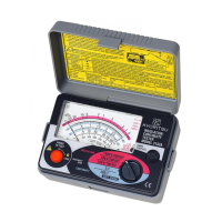
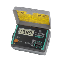
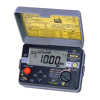
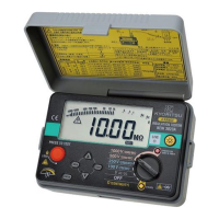
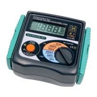
Instrument layout See Fig 1.
4.2
Resistance of test leads
The object of testing is to measure the resistance of parts of the wiring system
alone,and this should not include the resistance of any test leads used.The
procedure is to measure the resistance of the test leads and to subtract this
from the instrument reading which includes the lead resistance.Proceed as
follows:-
1.Press the test button once. Then, the instrument switches on.
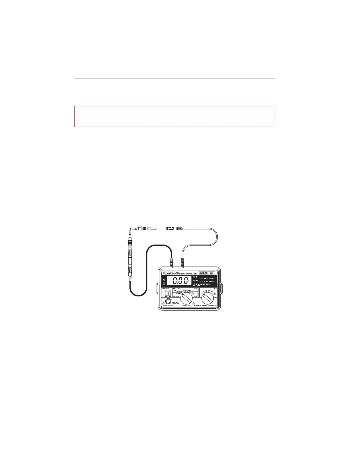
2. Connect the ends of the test leads in use firmly together(see Fig 2)and
operate the test button.
3. The display will read the resistance of the test leads,and a careful note
should be made of the reading.
Fig 2
www.GlobalTestSupply.com
Find Quality Products Online at: sales@GlobalTestSupply.com