—
14
—
◦ Electronic fluorescent starter switches
◦ Passive infra-red detectors (PIRs)
◦ Dimmer switches
◦ Touch switches
◦ Delay timers
◦ Power controllers
◦ Emergency lighting units
◦ Electronic RCDs
◦ Computers and printers
◦ Electronic point-of-sale terminals (cash registers)
◦ Any other device which includes electronic components.
5.3
Preparation for measurement
Before testing, always check the following:-
1.The“low battery”Indication“
”is not displayed
2.There is no visually obvious damage to the tester or to the test leads
3. Test the continuity of the test leads by switching to continuity test and
shorting out the lead ends. A high reading will indicate that there is a faulty
lead or that the fuse is blown.
4.
MAKE SURE THAT THE CIRCUIT TO BE TESTED IS NOT LIVE.
A
warning lamp is lit if the instrument is connected to a live circuit but test
the circuit as well!
5.4
Insulation resistance measurement
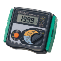
Model 6010A has a single test voltage of 500V DC.
1.Press the test button once. Then, the instrument switches on.
2. Select the insulation resistance setting by rotating the function dial to
“insulation”test section of the functional switch, after making sure that the
instrument is not connected to a live circuit.
3. Attach the test leads to the instrument and to the circuit or the appliance
under test (see Figs 7 & 8)
www.GlobalTestSupply.com
Find Quality Products Online at: sales@GlobalTestSupply.com