—
16
—
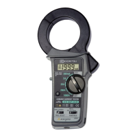
5- 4 How to Use The Frequency Selector Switch
KEW 2413R has a very good frequency response because of the
electromagnetic property of its transformers jaws. Therefore, it
measured, AC current not only of fundamental frequency of 50Hz or
60Hz, but of high frequencies and harmonics superimposed on the
fundamental frequency. To eliminate these superimposed components
and measure only in the fundamental frequency, KEW 2413R has a
Low pass filter circuit, which can be activated by setting the frequency
selector switch to the “50/60Hz” position. When the frequency selector
switch is set to “WIDE” , symbol “ ” is displayed on the LCD.
When the switch is set to “50/60Hz” , symbol “
” is displayed on the
LCD.
The Low pass filter has a cut-off frequency of approx. 100Hz and an
attenuation characteristics of approx. -24 dB/octave.
Note: -24dB/octave means that the magnitude of a signal declines by a
factor of 16 when its initial frequency doubles.
The frequency selector switch has the following two positions.
● WIDE(40Hz − over 1kHz):
Covers a wide frequency band from mains supply to high frequencies
generated by such equipment as inverters.
● 50/60Hz(40 − Approx.100Hz):
Filters out high frequency components to restrict measurement in
mains frequency band.
Note 3: The peak hold circuit of this instrument may not capture some
signals depending on phases because a half-wave rectifier
circuit is used.
Response characteristics are 10ms/ 100ms. Noises on higher
frequencies caused by inverters may not be captured. Readings
with Peak Hold off might become smaller or zero when
activating the Peak hold function, but this is not a malfunction.
 Loading...