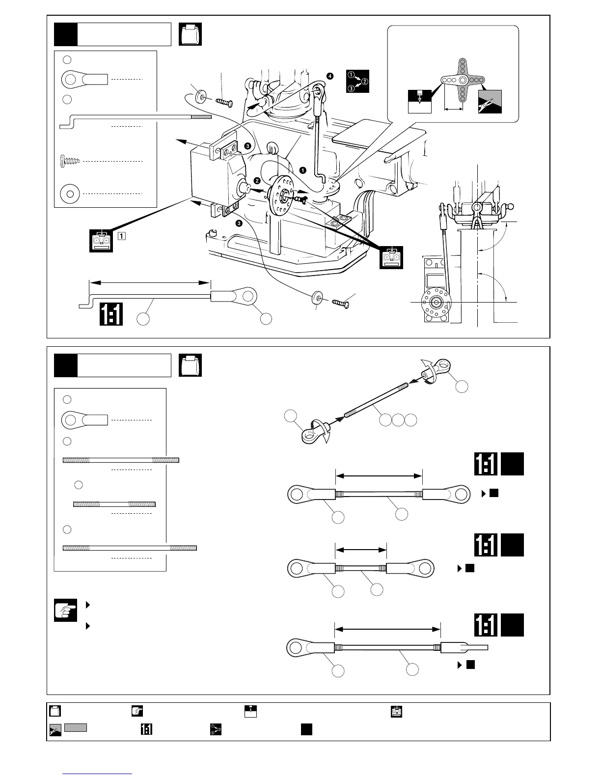
エルロンリンケージ
Aileron Linkage
17
18
ローターヘッド
Rotor Head
11
1
ボールエンド(L)
Ball End (L)
1
エルロンロッド
Aileron Rod
HH-1, HH-3
153A
27
●
ちがう形状のサーボホーンを
使用する場合。
With other types of servo horns:
HH-3
4
ボールエンド(L)
Ball End (L)
2
ピッチリンケージロッド
Pitch Linkage Rod
スタビライザーロッド
Stabilizer Rod
2
原寸図
True-to-scale diagram.
使用する袋詰。
Part bags used.
2mmの穴をあける(例)。
Drill holes with the specified diameter (here: 2mm).
2mm
をカットする。
Cut off shaded portion.
注意して組立てる所。
Pay close attention here!
番号の順に組立てる。
Assemble in the specified order.
フルセットには含まれています。それ以外は別購入品。
Only supplied in full sets.
ロッドの長さは左右同寸法にする。
Ensure both rods are equally long.
ロッドの長さはおおよその目安。
P16トラッキング調整で微調整する。
27
153A
2mm
6〜8mm
236
ヒラーコントロールロッド
Hiller Control Rod
2
237
235
27
(エルロンサーボ)
2.6mm
2
2.6 x 6mm TPビス
Screw
2.6mm ワッシャー
Washer
2
2.6 x 6mm
2.6 x 6mm
2.6mm
(Aileron Control Servo)
エルロンロッド
Aileron Rod
●
2セット組立てる(例)。
Assemble as many times as specified (here: twice).
x
2
約47.5mm
approx. 47.5mm
90°
90°
235
235
236
236
237
27
27
●ピッチロッド
PitchRod
約34mm
approx.34mm
●スタビライザーロッド
StabilizerRod
約20mm
approx.20mm
237
27
27
27
●ヒラーコントロールロッド
HillerControlRod
約41.5mm
approx.41.5mm
x2
x2
x2
で使用する。
The adjusting length of the rods are
only approximate values. The length
may vary according to the model.
Fine adjustment is required in tracking
adjustment on page 16.
Pitch Rods are
attached in
Step 21.
で使用する。
Hiller Control Rods are
attached in Step 19.
19
で使用する。
Stabilizer Rods are
attached in Step 21.
21
21
 Loading...