24
25
26
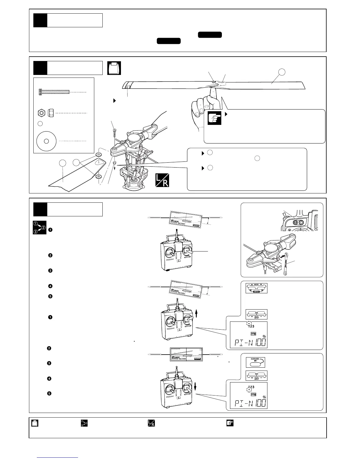
メインローター
MainRotor
メインローター
MainRotor
28
2.6mm
注意して組立てる所。
Pay close attention here!
14
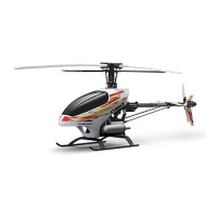
この段階で、ボディを取付けます。ボディの取付けは、組立説明書 をお読みになり、正しく取付けてください。
Now, mount the body. For this, please read the INSTRUCTION MANUAL.
●
2
2.6×18mm キャップビス
Cap Screw
2
2.6mm ナイロンナット
Nylon Nut
HH-1, HH-3
LO
W
-
PITC
H
(
0
°
)
RO
T
O
R
H
O
V
E
R
-PI
T
C
H
(
8
°)
H
I
GH
-
P
I
T
C
H
(
1
0
°
)
ピ
ッ
チ
ゲ
ー
ジ
の
ガ
イ
ド
ラ
イ
ン
が
ス
タ
ビ
ラ
イ
ザ
ー
バ
ー
と
平
行
に
な
る
ま
で
傾
け
る
。
O
n
l
y
t
h
e
g
u
i
d
e
l
i
n
e
t
h
a
t
i
s
p
a
r
a
l
l
e
l
t
o
t
h
e
s
t
a
b
i
l
i
z
e
r
b
a
r
,
i
n
d
i
c
a
t
e
s
t
h
e
p
i
t
c
h
a
n
g
l
e
o
n
t
h
e
r
o
t
o
r
b
l
a
d
e
s
.
GUIDEL
INE
R
T
H
E
F
I
N
E
S
T
R
A
D
I
O
C
ON
T
R
O
L
M
O
D
E
L
S
約8°
LOW-PITCH (
0
°)
ROTOR
H
O
VER-
P
IT
C
H
(
8
°
)
H
IG
H
-
P
IT
CH
(
1
0
°)
ピッチゲージのガイドラインがスタビライザーバーと平行になるまで傾ける。
Onlytheguidelinethatisparalleltothestabilizerbar,indicatesthepitchangle
ontherotorblades.
GUIDELINE
R
THE FINEST RADIO CONTROL MODELS
約0
L
O
W
-P
I
T
C
H
(
0
°
)
R
O
T
OR
H
O
V
E
R
-
PI
TC
H
(
8
°
)
H
I
G
H
-
P
I
T
C
H
(
1
0
°
)
ピ
ッ
チ
ゲ
ー
ジの
ガ
イ
ド
ラ
イ
ン
が
ス
タ
ビラ
イザ
ーバ
ーと平
行に
なる
まで
傾け
る。
O
n
l
y
t
h
e
g
u
i
d
e
l
i
n
e
t
h
a
t
i
s
p
a
r
a
l
l
e
l
t
o
t
h
e
s
t
a
b
i
l
i
z
e
r
b
a
r
,
i
n
d
i
c
a
t
e
s
t
h
e
p
i
t
c
h
a
n
g
l
e
o
n
t
h
e
r
o
t
o
r
b
l
a
d
e
s
.
G
UI
DE
L
I
N
E
R
T
H
E
F
I
N
E
S
T
R
A
D
I
O
C
O
N
T
R
O
L
M
O
D
E
L
S
約10〜11°
軽い方にデカールをはる。
Place some tape to the lighter
of the blades.
2.6×18mm
テープ
Tape
2.6×18mm
28
152
左右同じように組立てる。
Assemble left and right sides
the same way.
の取付け向きに注意。
Notethedirectionfor.
が動く程度に締め、強く締めすぎないこと。
Tighten both 2.6×18mm cap screws ensuring
the main rotor blades still have a little play in the
grips. Do not overtighten.
28
28
28
使用する袋詰。
Part bags used.
番号の順に組立てる。
Assemble in the specified
order.
メインローターピッチ角の調整●
ハイピッチ
High Pitch
ハイピッチ+または−キー
で調整する
Adjust high pitch with
+or−key
ローピッチ+または−キー
で調整する
Adjust low pitch with
+or−key
1回押し
Press cursor button once
approx.10〜11°
approx.8°
approx.0
ホバーピッチ
Hover Pitch
中立位置
Neutral
ローピッチ
Low Pitch
スロットルスティックを中央にする。
メインローターにピッチゲージを差し込み、メ
インローターの角度が約8°になるようにホバー
ピッチトリム又は、2本のピッチロッドを調整
する。
スロットルスティックをハイにする。
メインローターの角度が約10 〜11°になるよ
うに、送信機で調整する。
スロットルスティックをスローにする。
メインローターの角度が約 2〜0°になるよう
に、送信機で調整する。
調整が終わったら、受信機、送信機の順番で電
源を切り、ニカドバッテリーをはずす。
モーターとモーターコントロールアンプのコネ
クターを接続する。
Move the throttle control stick to
neutral.
Put the pitch gauge on each main rotor
blade.
Adjust the length of both pitch rods or
HovpitchTrimsothepitchangleis8.
Move the throttle control stick to high.
Adjust on the transmitter a pitch angle
of10to11.
Move the throttle contol stick to slow.
Adjust on the transmitter a pitch angle
of2to0.
Whentheadjustmentsaredone,switchoff
the receiver and transmitter and unplug
theNi‑Cdbattery.
Connecttheelectricmotorandelectronic
speedcontroller.
ボディ編
バランス調整が不完全だと振動の原因になり、
色々なトラブルの原因になります。安全のため
調整は正確に行ってください。
If the main rotor blades are not perfectly balanced,
vibration, loose screws and radio trouble are the
consequences.
4
グリップスペーサー
Grip Spacer
152
Pitch angle adjustment on the main rotor.●
BODY
ピッチロッド
Pitch Rod
ホバーピッチトリム
HOV Pitch Trim
▲▼
同時押し
▲5回押す
Press ▲▼ buttons at the
same time then press ▲5
times.
 Loading...