Do you have a question about the Kzyee KM10 and is the answer not in the manual?
Details the display, operating/storage temperatures, power, dimensions, and weight.
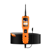
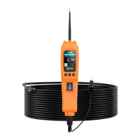
Identifies and describes the probe tip, headlights, polarity indicator, LCD, power switch, mode button, ground lead, and adaptor.
Lists the included parts with their descriptions and quantities.
Explains the tool's function for diagnosing electrical systems and its key capabilities.
Details how to connect the tool to the vehicle's battery for power.
Guides on performing a self-test to ensure the tool is functioning correctly.
Explains the auto circuit breaker feature for overload protection and tool safety.
Describes the four diagnostic modes: DC voltage, AC voltage, resistance, and diode testing.
Instructions for testing voltage and polarity in circuits using the tool's LEDs and LCD.
How to test continuity of wires and components using the tool in resistance mode.
Procedure for testing sensor circuits, like MAP sensors, using AC voltage mode.
Steps to activate components directly when not installed in a vehicle.
Procedure for activating electrical components within the vehicle using the tool.
Guidance on testing trailer light functions and connections using the tool.
How to activate components by applying ground through the tool's probe.
Explanation of the Red/Green Polarity LED function and its voltage comparison.
Methodology for tracing and identifying short circuits in vehicle wiring.
Procedure for identifying poor ground connections using the tool's indicators.
| Category | Test Equipment |
|---|---|
| Type | Digital Multimeter |
| Display | LCD |
| Auto Power Off | Yes |
| Backlight | Yes |
| Data Hold | Yes |
| Diode Test | Yes |
| Continuity Test | Yes |
| Functions | Voltage, Current, Resistance, Capacitance, Frequency, Diode Test, Continuity Test |
| Operating Temperature | 0°C to 40°C |
| Frequency Range | 10MHz |
| Safety Rating | 600V |
| Model | Kzyee KM10 |
| Current Range | AC/DC Current: 600μA/6000μA/60mA/600mA/10A |