Vehicle Super Probe
- 10 -
There is also another way to prove continuity of connections to ground or battery.
Power up the connection using the power switch. If the circuit breaker trips you know
that you have a good solid low resistance connection.
Note: You can use the probe tip to pierce the plastic insulation on a wire. This means
that you can test the circuit without disconnecting anything.
3.3 Signal Circuit Testing
Once you extract a DTC from the vehicle and realize that troubleshooting begins with
some kind of sensor circuit, there is a quick test you can perform to verify the code.
Testing your sensor is easy while using the tool.
For example, you suspect there is a problem with your M.A.P.? sensor circuit, then
follow the procedure involved with testing this sensor:
◆ Set the tool in AC Voltage mode, using the probe tip with chassis ground or the
auxiliary ground lead.
◆ Connect vacuum pump to MAP sensor.
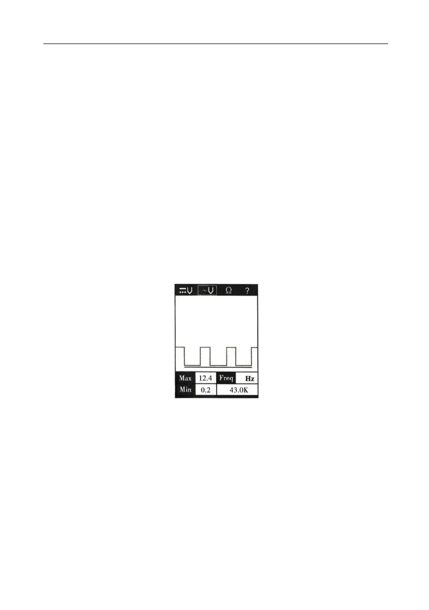
◆ Contact the probe tip to the MAP sensor positive terminal and observe the LCD
readings which should be a sine wave in normal condition.
◆ Apply vacuum.
◆ Release vacuum and observe the LCD readings. ( Figure 10)
Figure 10
If the LCD readings are abnormal, there is a problem with this sensor.
3.4 Activating Components in Your Hand
While the tool is in DC voltage mode, by using the probe tip in connection with the
auxiliary ground lead, components can be activated right in your hand, thereby
testing their functions.
Connect the auxiliary ground lead to the negative terminal or ground side of the
component being tested. Then contact the probe tip to the positive terminal of the
component, the green LED should light, indicating continuity through the component.
While keeping an eye on the green LED,quickly press and release the power switch
forward. If the green LED went out and the red LED came on, you may proceed with
further activation. Rock the power switch forward and hold it down to provide power