Do you have a question about the Labconco Guardian 1000/1 and is the answer not in the manual?
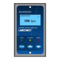
Describes the back-lit, full graphic unit with visual display.
Displays for Sash High, Ext Alarm, Air Fail, High Air, and Set-back.
Mains Fail, Low Temp, High Temp indicators.
LED Indicators, Audible Alarm, Enter, and +/- buttons.
Configurable relay input for alarm disable, sash high, etc.
Configurable relay input for alarm disable, sash high, etc.
Configurable relay input for alarm disable, sash high, etc.
Configurable volt-free relay output.
Configurable volt-free relay output.
Configurable volt-free relay output.
Describes accessing menus via password and using +/-/Enter buttons.
Procedure to escape from Calibration or Configure Menu by accident.
Details the power-up sequence, self-test, and stabilization period.
Explains the two options after the delay: normal operation or setup mode.
Meter reading above warning level with Green LED on.
Meter reads between warning and air fail levels with Amber LED on.
Meter below alarm level, AIR FAIL display, Red LED flashing.
How the Low air alarm resets automatically when airflow increases.
Describes High Air toggles, audible alarm mute, and relay operation if configured.
Icon shown on display when audible alarm is muted via Enter button.
Amber LED on, Sash High toggles on/off with velocity display.
Muting audible alarm via Enter, initiating a repeat timer.
Display icon shows High or Low, relay operates if configured.
Night-back Icon displayed, Red LED on, audible alarm muted.
Red LED on, External Alarm toggles on/off, audible alarm can be muted.
Alarm disabled displayed, Red LED on, audible alarm muted.
Red LED on, Close Sash toggles on/off, audible alarm sounds.
Optional feature indicating power failure, Red LED on, audible alarm sounds.
Optional feature for High/Low Temp alarms with display and LED indications.
Instructions for preparing the fume hood for the alarm system.
Instructions for mounting the monitor to the corner post.
Steps for connecting the air sensor, adaptor, and hose.
Instructions for wiring the electrical cover plate and junction box.
Connecting power supply and replacing the front panel.
Steps to access calibration mode via password entry.
Instructions on following the display for unit calibration.
Unit returns to Main Menu upon completion of calibration.
How to select 'RUN' to start displaying face velocity.
Opening sash to normal max safe height for low air sample.
Closing sash to approx 50% for higher air sample.
Acceptable variations in face velocity readings across the measuring grid.
Allowing velocities to stabilise during calibration sampling.
Opening horizontal sliding sashes for low air sample.
Importance of adapter/hose connection for sensor to detect airflow changes.
Calibrating with face velocity differences of at least 20 fpm.
Recommended low air alarm and calibration set points.
Changing sample differences and sensor difference settings.
Adjusting low air alarm, caution, and warning reset points.
Entering "DONE" to finalize configuration settings.
Entering "CALIBRATION" mode from the SETUP menu.
Measuring and entering low face velocity by altering sash position.
Measuring and entering high face velocity with sash position changes.
Entering "DONE" after setting low and high points, then selecting "RUN".
Using an anemometer to confirm display accuracy at various sash positions.
Steps to access the Cal Config menu via Enter, Setup, Configure, Password.
Setting face velocity display units to fpm or m/sec.
Setting the low air alarm velocity value.
Inhibits display below a selected value when enabled.
Setting the warning air alarm velocity value.
Value to reset to Air Safe above Air Fail alarm point.
Enables and sets the high air alarm velocity value.
Monitors airflow fluctuations during low air calibration.
Monitors airflow fluctuations during second air calibration.
Sets the difference required between airflow samples during calibration.
Time delay for Low Air alarm activation.
Time delay for air to reset to Air Safe from Warning.
Enables/disables face velocity reading on display.
Enables/disables the time line display.
Enables/disables the audible alarm.
Checks sensor output change between calibration points.
Reduces monitor scale effect on airflow display.
Provides rear view dimensions of the SM6 sensor.
Specifies dimensions for panel cutout.
Details front view cutout dimensions for the SM6 sensor panel.
Connection for 0-10V retransmission output.
Connections for R1, R2, R3 volt-free relay outputs.
Connections for Input 1, Input 2, Input 3 for switches and contacts.
RS485 COM PORT connector for Modbus RTU or BACnet.
RJ11 plug for SM6 Airflow Sensor connection.
Connection for 120VAC power supply (15VDC Output).
Optional connection for 0-10V retransmission output.
Connections for R1, R2, R3 volt-free relay outputs.
Connection for the optional temperature sensor to Input 3.
Connections for Input 1, Input 2, Input 3.
RS485 COM PORT connector for Modbus RTU or BACnet.
RJ11 plug for SM6 Airflow Sensor connection.
Connection for 120VAC power supply (15VDC Output).
Connection for 0-10V retransmission output.
Connections for R1, R2, R3 volt-free relay outputs on the interface unit.
14-way ribbon cable connecting the monitor to the relay interface unit.
Input connections on the relay interface unit.
RJ11 plug for SM6 Airflow Sensor connection.
Connection for 120VAC power supply (15VDC Output).
Settings for display units, alarms, fluctuations, timing, and sensitivity.
Lists default values for various configuration parameters.
Settings for temperature units, low/high temp alarms, and display.
Settings for input functions and output relay activation.
Configuration for alarm relays and associated timers.
Settings for external alarms, display icons, and sensor error handling.
Settings for sash repeat and warning timers.
Lists exclusions from the limited warranty.
Outlines limitations of liability and exclusive remedies.
Contact information for Holland Safety Equipment.
Export sales contact information for Temperature Electronics Ltd.
| Brand | Labconco |
|---|---|
| Model | Guardian 1000/1 |
| Category | Measuring Instruments |
| Language | English |