AQ-00073-000, Rev. 7 5
circuit board and lift the plate out of the instrument.
4. Install the new side plate, Part No. EC-12201-000, into the instrument in the same
orientation as the original plate.
5. Reconnect the large ribbon cable into the same header connector located on the
newly installed side plate.
6. Remove the cable running from the detector module to the motherboard header at
P9. This cable will not be used.
7. Plug the single connector end of Part No. AS-01803-000 into the header at the
detector module.
8. Connect the gray 16-pin connector on the opposite end of Part No. AS-01803-000
into the P9 header on the motherboard.
9. Connect the remaining black connector end of Part No. AS-01803-000 into the
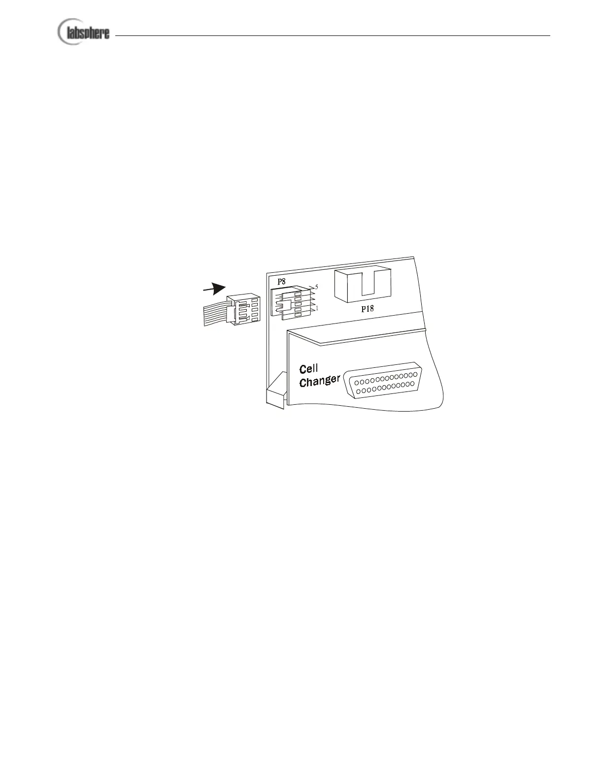
newly installed accessory side plate header labeled P8 as shown in Figure 4.
10. Plug the gray connector on Part No. AS-01803-100 into the side plate header
labeled P18. Note that this connector is keyed.
11. Route the black connector of Part No. AS-01803-100 to the instrument mother-
board at P8. This connector is keyed.
12. The individual wires attached to Part No. AS-01803-100, labeled +5V and GND,
should be plugged into the motherboard electrical studs labeled +5V and GNDA
respectively.
13. Tighten the two mounting screws that secure the side plate to the instrument enclo-
sure.
14. Proceed to the accessory installation procedure.
Kit Modifications to the Lambda 20 and Lambda 40 Spectrometers
The accessory kit and associated cables for modification to the Lambda 20 and Lambda 40 spec-
trometers are provided by PerkinElmer. Consult your PerkinElmer technician for installing the
accessory kit for these instruments.
Figure 4. Making the detector cable hookup to the side plate.