AQ-00073-000, Rev. 7 8
Diagnostic Scans
This section of the instruction manual contains the procedures for a series of diagnostic scans on
your accessory. These scans were performed on your accessory and our instrument before we
shipped the RSA-PE-20 to you.You should perform these scans again on your instrument after
installing the accessory to validate proper operation of the accessory. The scan results should be
retained for future use. If problems develop with your accessory in the future, repeat the diagnos-
tic scans and send us copies for analysis.
The quality assurance documentation includes a copy of the diagnostic scans we performed at
Labsphere. The instrument parameters used for each diagnostic scan are listed under the test
results. You should use these same parameters for your diagnostic scans. The user should note
that a background correction is executed as part of the 100% Baseline Scan and used for all sub-
sequent diagnostic scans.
Sample Beam Energy Scan
The energy scan is an indicator of accessory throughput.
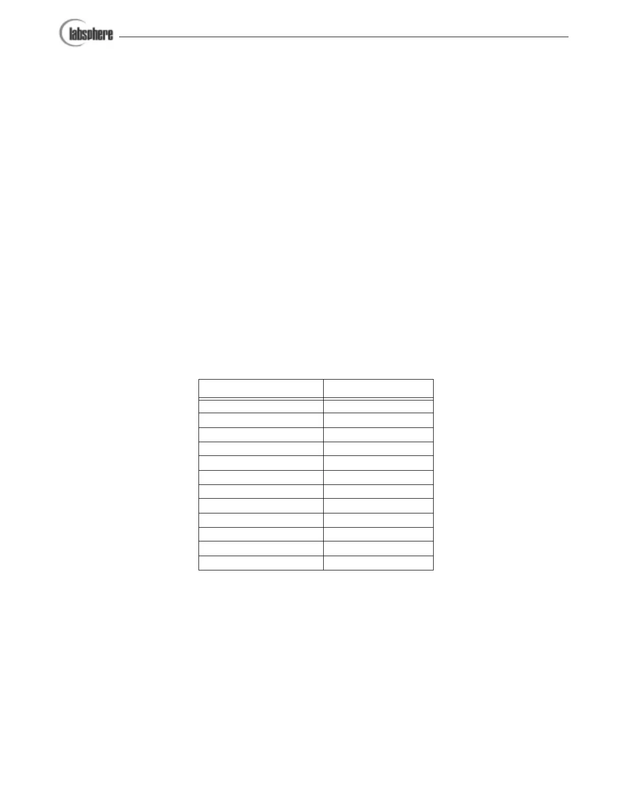
1. Set up instrument parameters to conform to those listed in Table 1. These parame-
ters settings should be identical to those listed in the quality scans accompanying
your shipment.
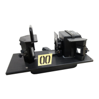
2. Load the reflectance standard at the sample reflectance port. The 8° wedge should
be installed.
3. Close the sample compartment door. Execute a scan from your UV Winlab soft-
ware and save the results.
Instrument Parameter Setting
Lamps UV/Vis ON
Beam Single Beam
Method Scan
Data Interval 1 nm
Abscissa Start 250
Abscissa End 1100
Slit Mode Fix
Slit 2 nm
Integration Time 0.08 s
Ordinate Mode E1
Sample Beam Front
Attenuators 100%
Table 1. Instrument setup for sample beam energy scan.