AQ-00073-000, Rev. 7 7
WARNING:
Do not touch the mirror surfaces with your bare fingers.
3. Configure the instrument for white light operation by entering 0 nm in the Instru-
ment section of the Lambda Manual Control Display.
4. Dim the room lights.
5. Place a piece of white translucent tissue paper in front of mirror M2. Adjust the
thumbscrews on M1 so the beam is centered.
6. Place the white paper in front of mirror M3. Adjust the thumbscrews of M2 so that
the beam is centered on mirror M3.
7. Place the white paper in front of the transmittance port of the sphere. Adjust the
thumbscrews of M3 so that the beam enters the transmittance port without clipping
the edges of the port. The transmittance port can be viewed by looking into the
sphere through the front reflectance port.
8. Place a piece of lens paper at the reflectance port. Adjust the thumbscrews of mir-
ror M3 so that the beam is centered on the reflectance port. If the beam can not be
centered, repeat the previous steps making minor adjustments in either direction so
the beam is centered on the reflectance port and is not clipped at the transmittance
port.
9. The accessory is now properly aligned. You can now proceed to the next section on
diagnostic scans.
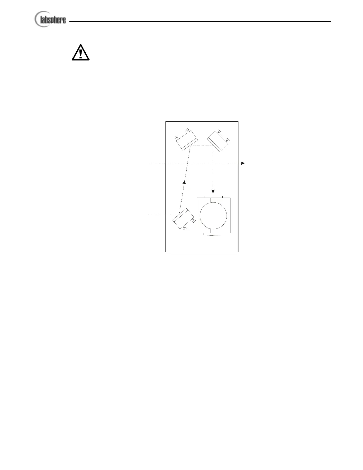
M1
M2
M3
Sample Beam
Reference Beam
Transmittance
Port
Reflectance
Port
Integrating Sphere
Figure 6. Optical setup of the RSA-PE-20 accessory. Make sure
your UV Winlab software is configured for the sample beam at
the front port.