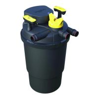
Max-Flo 2000/7500, 2400/9000, and 2900/11000 (Fig. 3)
1) Using a Phillips (cross-headed) screwdriver, unscrew the four
screws on the impeller cover (4) and remove it
2) Using a flathead screwdriver, carefully lift out the impeller
assembly.
3) Clean all components in clean water only, using a small, non-
abrasive brush, if necessary. DO NOT USE DETERGENTS OR
OTHER CHEMICAL CLEANERS which could damage the pump
and pollute the pond
4) Reassemble all components with care (see
Closing the Pump
Cage
), ensuring that the impeller bearing, bushing and O-Ring
are correctly placed at the bottom of the impeller well.
Replacing the Bushing and O-Ring
(Replacement pack not included. Part # PT-466).
For Max-Flo
1500/6000,
2000/7500, 2400/9000 and
2900/11000 only
Though the bushing is made of very resistant material, it is prone to
wearing in certain conditions. For this reason, it is recommended
that you replace it whenever the impeller unit is replaced. Follow the
instructions provided with the replacement parts package. Once you
have replaced the Bushing and O-Ring, reassemble all parts with
care (see Fig. 3 &
Closing the Pump Cage
).
Volts 120 230-240 120 230-240 120 230-240 120 230-240 120 230-240 120 230-240
Hertz 60 50 60 50 60 50 60 50 60 50 60 50
Watts 32 32 65 55 100 80 100 100 100 100 130 125
Maximum depth 6’6”/2 m 6’6”/2 m 6’6”/2 m 6’6”/2 m 6’6”/2 m 6’6”/2 m
Max flow rate
Max head
Degree of protection IPX8 IPX8 IPX8 IPX8 IPX8 IPX8
MAX-FLO PUMP 600/
2200
900/
3500 1500/6000 2000/7500 2400/9000 2900/11000
PT-340 PT-342 PT-344 PT-346 PT-348 PT-350
US GPH
LPH
ft
m
899
3400
6’4”
1.95
977
3700
6’2”
1.9
582
2200
5’10”
1.8
582
2200
5’10”
1.8
11’6”
3.50
1585
6000
13’5”
4.10
1558
5900
12’2”
3.7
1981
7500
12’2”
3.7
1981
7500
12’2”
3.7
2378
9000
12’2”
3.7
2378
9000
14’9”
4.5
2853
10800
14’9”
4.5
2800
10600
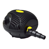
Closing the Pump Cage
Place the pump inside the bottom half of the cage. Ensure that the
electrical cord is properly seated inside the recess located on the
bottom half of the cage.
At a 45° angle, join the top half of the cage to the bottom half of
the cage by first aligning the two posts, located on the top half of
the cage, with the two docking holes, located at the bottom half of
the cage. Close the cage completely, ensuring that both halves are
fully aligned. Lock the pivot pin fasteners as explained in
section called
Opening and Closing the Pump Cage
.
Ensure that the pump cage is securely locked and the electrical cord
is seated properly in position before lifting or operating the pump.
TROUBLESHOOTING
LOW FLOW FROM PUMP
• Check that the pump cage is clean
• Check the hose for blockages
• Check that the pump is free of dirt and debris
NO FLOW FROM PUMP
• Check that the power supply is on
• Check the fuse (UK market only) and wiring
• Check that the plug is correctly connected to the electrical
receptacle/socket
• Check that the pump cage is clean
• Check the hose for blockages
• Check that the pump is free of dirt and debris
• Check that the pump is completely immersed in water
WARRANTY
The Pumps are guaranteed against defects in material or
workmanship for a period of 3 years from date of purchase,
under normal usage. PowerJet Pumps will be repaired or
replaced at manufacturer’s discretion, free of charge. This
warranty does not apply to any PowerJet Pump which has
been subjected to misuse, negligence, tampering or accidental
damage to the impeller or impeller shaft. No liability is
assumed with respect to loss or damage to livestock or
personal property irrespective of the cause thereof. This
warranty does not affect your statutory rights. Failure caused
by misuse is not covered by this warranty.
65
CASCADE
ABC
D
G
H
F
E
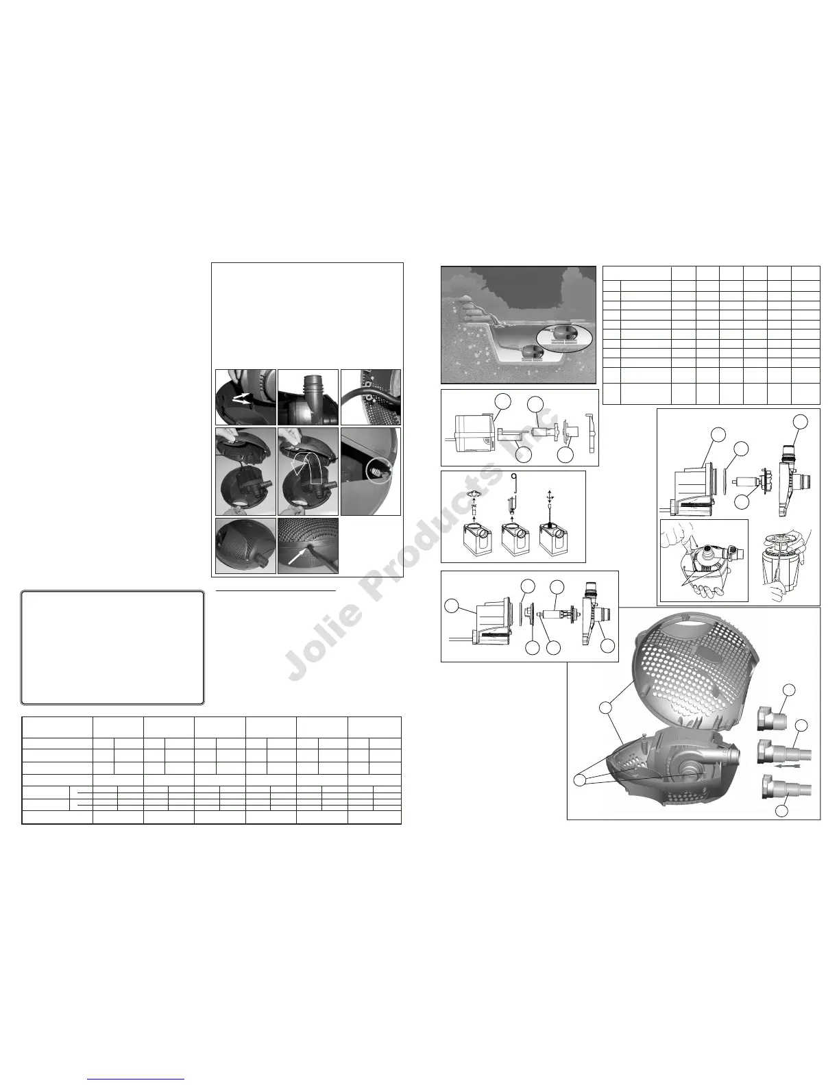
600/2200 900/3500 1500/6000 2000/7500 2400/9000 2900/11000
PT-340 PT-342 PT-344 PT-346 PT-348 PT-350
1 Moteur PT-382 PT-384 PT-388 PT-390 PT-392 PT-394
2 Joint d’étanchéité – PT-762 PT-763 PT-764 PT-764 PT-764
3 Couronne PT-455 PT-457 PT-459 PT-461 PT-461 PT-465
3A Arbre de la couronne PT-759 PT-761 – – – –
4 Couvercle de la couronne PT-737 PT-738 PT-733 PT-735 PT-739 PT-739
5
Couvercle du puits de la couronne
– PT-768 – – – –
6 Boîtier de la pompe PT-439 PT-444 PT-445 PT-446 PT-446 PT-446
7 Axes d’articulation PT-447 PT-447 PT-447 PT-447 PT-447 PT-447
8
Raccord auto-bloquant (38 mm)
– – – PT-638 PT-638 PT-638
9 Raccord universel – – – PT-640 PT-640 PT-640
(19, 25, 32 mm)
10
Accouplement rigide universel
PT-636 PT-636 PT-636 – – –
(19, 25, 32 mm avec adapteur pour
raccord auto-bloquant de25 mm
PIÈCES DE RECHANGE
6
7
9
8
10
Fig.4
2
3
4
1500/6000
2000/7500
2400/9000
2900/11000
1
Fig.3
Fig.1
1
3A
3
4
600/2200
900/3500
2
5 3A
3
4
1
Fig.2
Pour retirer l’arbre de la
couronne, utiliser l’outil fourni.
Fig.1A
VIS
VIS