31
4 CMS Components
Part number
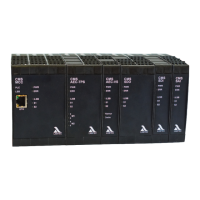
MCC – Master Control Component Type 668R1000-XX
*
* XX = depends on configuration
Function
Supply voltage
MCC
Inputs
Outputs
24 VDC +/20%, SELV
230 V/120 V +10/15%, 47–63 Hz, 24 VDC ±20%
230 V/120 V +10/15%, 47–63 Hz, 24 VDC ±20%
Maximum backup fuse/outputs 8 A fast-acting
Current draw Min: 200 mA
Max: 335 mA
Power consumption max. 10 W
Digital inputs Nominal
current:
2.3 mA (230 VAC), impedance 100 k
2.1 mA (120 VAC), impedance 100 k
2.1 mA (24 VDC), impedance 100 k
Since the inrush currents on the are low, use gold-plated silver
contacts.
Signal ON: 0.78 mA (230 VAC) 77 VAC
0.97 mA (120 VAC) 56 VAC
0.55 mA (24 VDC) 6.9 VDC
Signal OFF: 0.35 mA (230 VAC) 36 VAC
0.35 mA (120 VAC) 21 VAC
0.27 mA (24 VDC) 4 VDC
Digital outputs I
max
= 2 A per output, but not to exceed 8 A in total
cos 0.2
Residual voltage possible due to self-test function.
Flame sensor input Optical: Flame sensor connection FFS07 or FFS08
U
nom
= 27 V ±1 V
Ionisation: 230 VAC (120 VAC) supply voltage
I
min
= 1 A
I
max
= 50 A
Cable length max: 300 m, shielded.
Current output 0 - 20 mA ±2%
Output current max: 25 mA
Load max: 1 k
Use shielded cables only!
Analogue input Multifunctional input for the connection of:
– Potentiometer (2 k … 10 M)
– TPS (see wiring diagram chapter)
– Power input 0/4 - 20 mA, Ri = 150 – Voltage input 0 - 10 V, Ri = 100
M
Reference voltage 10 V, short-circuit proof
Tolerance ±2%
Use shielded cables only!
Fieldbus MODBUS TCP
LAMTEC SYSTEM BUS
Other Fieldbus protocols using separate modules

 Loading...