83
5 Functional Description with Process Diagrams
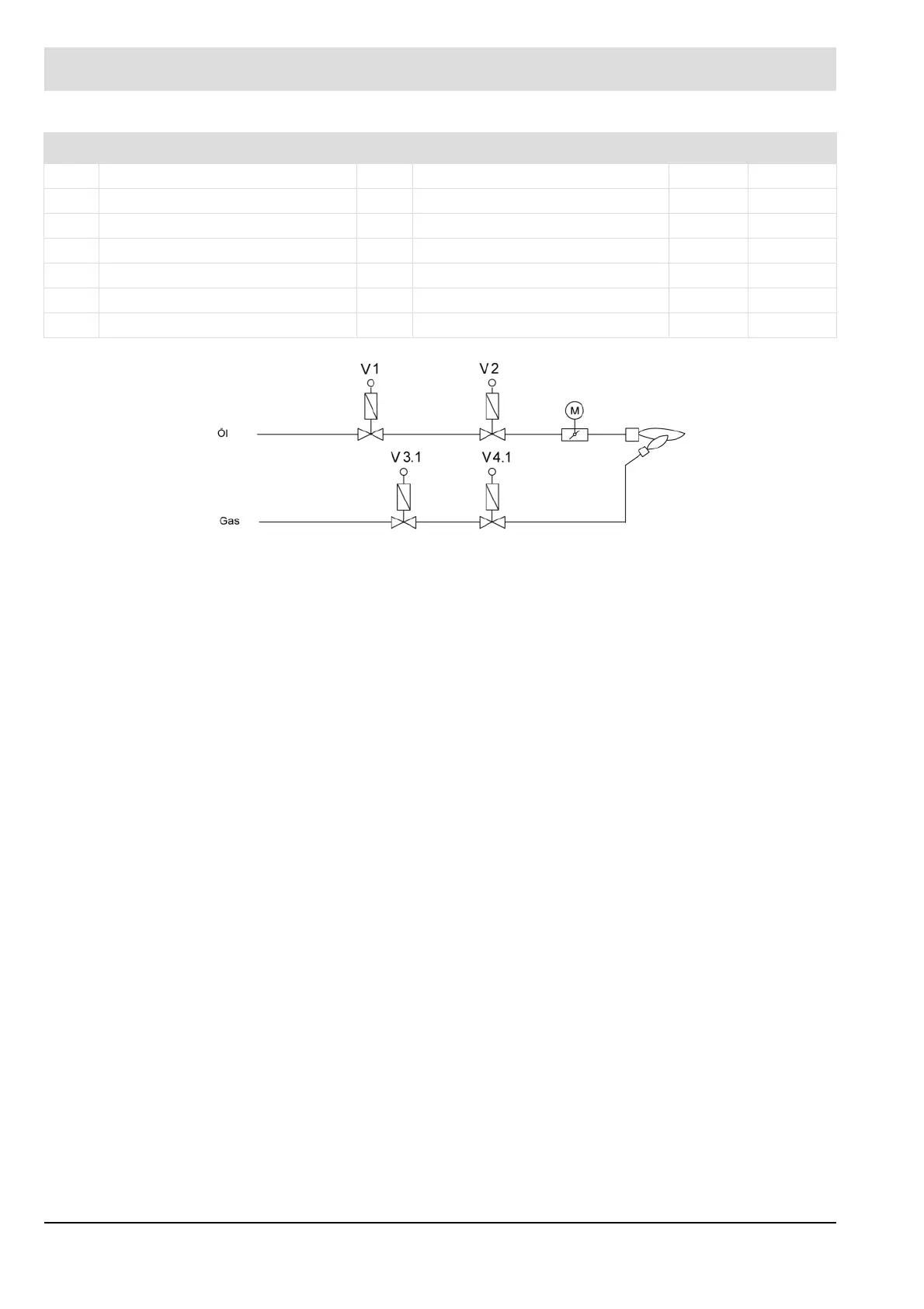
Fig. 5-6 Oil train for standard process flow oil modulating with pilot burner
t8 Stabilization time P310 3.0 s
t9 2
nd
safety time P308 3.0 s
t11 Control release delay time P380 0.0 s
t12 Block and bleed of the gas train P334 3.0 s
t13 Post-ventilation time P319 0.0 s
t22 Program monitoring time P304 600 s
t23 Irrelevance time P323 2.0 s
Signal bar Significant times and their parameters Standard
V1 Fuel valve on oil side M Actuator drive for gas damper
V2 Fuel valve on burner side
V3 Pilot valve on gas side
V4 Pilot valve on burner side