EasyManua.ls Logo

Landis+Gyr 2WR5 User Manual

Landis+Gyr 2WR5
3 pages
To Next Page IconTo Next Page
Page #1 background imageLoading...
Page #1 background image
Ultrasonic Heat Meter 2WR5
Operating instructions
UH 302-101l
These operating instructions have to be handed over to the end user
The heat meter 2WR5 combines state of the art
microcomputer technology with innovative ultrasonic
metrology avoiding any moving mechanical parts.
This technology is therefore non-wearing and largely
maintenance-free. High accuracy and long-time
stability ensure correct and fair heating cost
accounting.
The quantity of heat output from the heating water
is proportional to the difference in temperature
between the supply and return temperatures and the
volume of heating water having flowed.
The heating water volume is measured by an
ultrasonic pulse that is first sent in the direction of
flow and then against the direction of flow.
With the flow the signal transmission time between
the transmitter and receiver is reduced and against
the flow it is increased.
The volume of heating water and the temperature
difference between the supply and return are then
multiplied and the product is added to the running
total.
The result is the quantity of heat consumed. This
result is recorded and displayed in physical units
kWh / MWh or in MJ / GJ.
Display
The heat meter display is subdivided into several
levels and may differ from the standard shown
below. The user loop display (level 1) is advanced
cyclically each time the button is pressed briefly.
User loop
Accum. qty of thermal energy
Tariff register, here, e.g. cold
Accumulated volume
Segment test
Error with/without error digit
The tariff displays can vary depending on the tariff
type. The displays shown here are for a combined
heat/cold meter. The valid tariff status is displayed
together with the thermal energy as _ ,
=
or
.
.
With a pure flow meter the heat and tariff registers
are not displayed.
If button is held pressed for three seconds, the
display switches from the user loop to the service
loops (level 2).
Service loops
Service loop 1
Service loop 2
Service loop 3
One of the service loops is preselected by pressing
the button briefly. By pressing the button for another
3 s the contents of the selected service loop will be
displayed.
Each time the button is pressed briefly the next
information is displayed.
The service loops are exited by holding the button
pressed for 3 s or automatically after 30 minutes.
3250 002 101 g
motralec
4 rue Lavoisier . ZA Lavoisier . 95223 HERBLAY CEDEX
Tel. : 01.39.97.65.10 / Fax. : 01.39.97.68.48
Demande de prix / e-mail : service-commercial@motralec.com
www.motralec.com
Question and Answer IconNeed help?

Do you have a question about the Landis+Gyr 2WR5 and is the answer not in the manual?

Landis+Gyr 2WR5 Specifications

General IconGeneral
BrandLandis+Gyr
Model2WR5
CategoryMeasuring Instruments
LanguageEnglish

Summary

Ultrasonic Heat Meter 2WR5

Display Navigation and User Interface

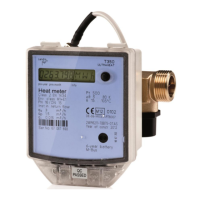
Explains the heat meter display structure, user loop, and service loop navigation via button presses.

User Loop Display

Details the primary display level (level 1) showing thermal energy, tariff, volume, and segment test.

Service Loops Navigation

Describes accessing and navigating secondary display levels (level 2) for detailed operational data.

Service Loop Details

Service Loop 1 Data

Lists current flowrate, heat output, temperatures, property number, and historical data for previous years.

Service Loop 2 Monthly Values

Explains how to access and view monthly operational values for the past 36 months.

Service Loop 3 Parameters

Details configuration parameters like pulse settings, temperature intervals, and M-bus addresses.

Monthly Value Storage

Describes monthly storage of heat, tariff, volume, max flowrate, max demand, and max temperatures.

Error Codes and Troubleshooting

Details error messages (F0-F9) and their meanings, advising to contact service for faults.

Operational Details and Specifications

Response Limits and Data Summations

Details response limits, flow rate, temperature difference, and conditions for heat/volume summation.

Yearly Set Day Memory Function

Explains how meter readings for heat and volume are stored in a previous year's memory.

Display of Measured Values

Covers acquisition and display of flow rate, heat output, temperature difference, and error indicators.

Time Tracking and Module Information

Describes operation time, downtime, property number, unit number, module type, and firmware version.

Additional Information

Cleaning and Maintenance

Advises using a soft, wet cloth without aggressive detergent for cleaning the calculator exterior.

Regulatory Compliance

Lists compliance with Measuring Instruments, EMC, and Low Voltage directives, and type-examination certificate.

Related product manuals