Installation and commissioning 23/30
D000011142 en k – E65C CU-B1, B2, B4 – User Manual © Landis+Gyr
Withdrawing of connection wires
Never withdraw connecting wires with the terminal closed, since this could
damage the terminal.
5.4.2 Connecting the communication interfaces
Insert the connecting cable with the RJ12 connectors in the relevant sock-
ets (RS232 left, RS485 right) until the connectors can be heard to engage.
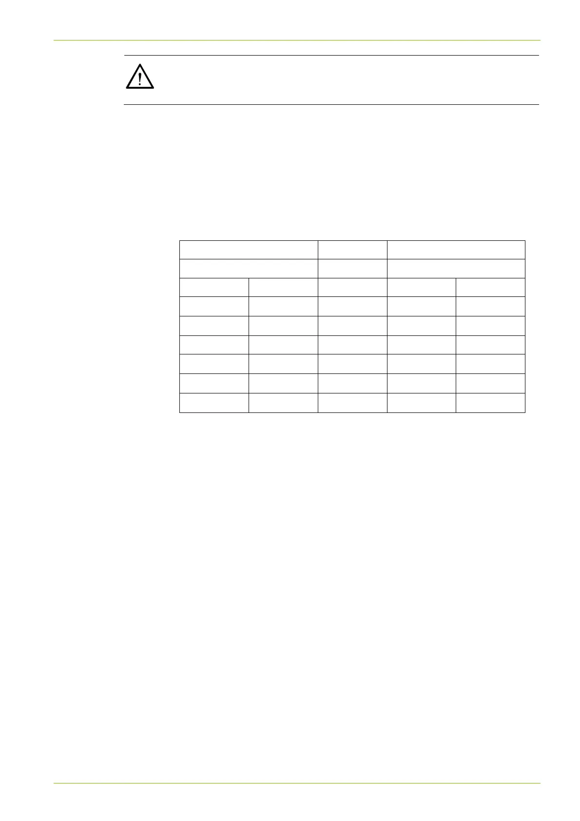
5.4.3 Pin allocation RS232
Connection to PC, terminal or laptop
Data receiver Meter with CU-Bx
DB-9 socket RJ12 socket
Pin Signal Direction Pin Signal
7 RTS
1 CTS
2 RxD
2 TxD
5 GND 3 GND
6 DSR
4 DTR
3 TxD
5 RxD
4 DTR
6 DSR
Significance of signals:
CTS Clear To Send
RTS Request To Send (for connection to modem)
TxD Transmitted Data
RxD Received Data
DTR Data Terminal Ready (Data Terminal = PC, terminal, laptop)
DSR Data Set Ready (Data Set = modem)
GND Signal ground