8/30 Device description
© Landis+Gyr D000011142 en k – E65C CU-B1, B2, B4 – User Manual
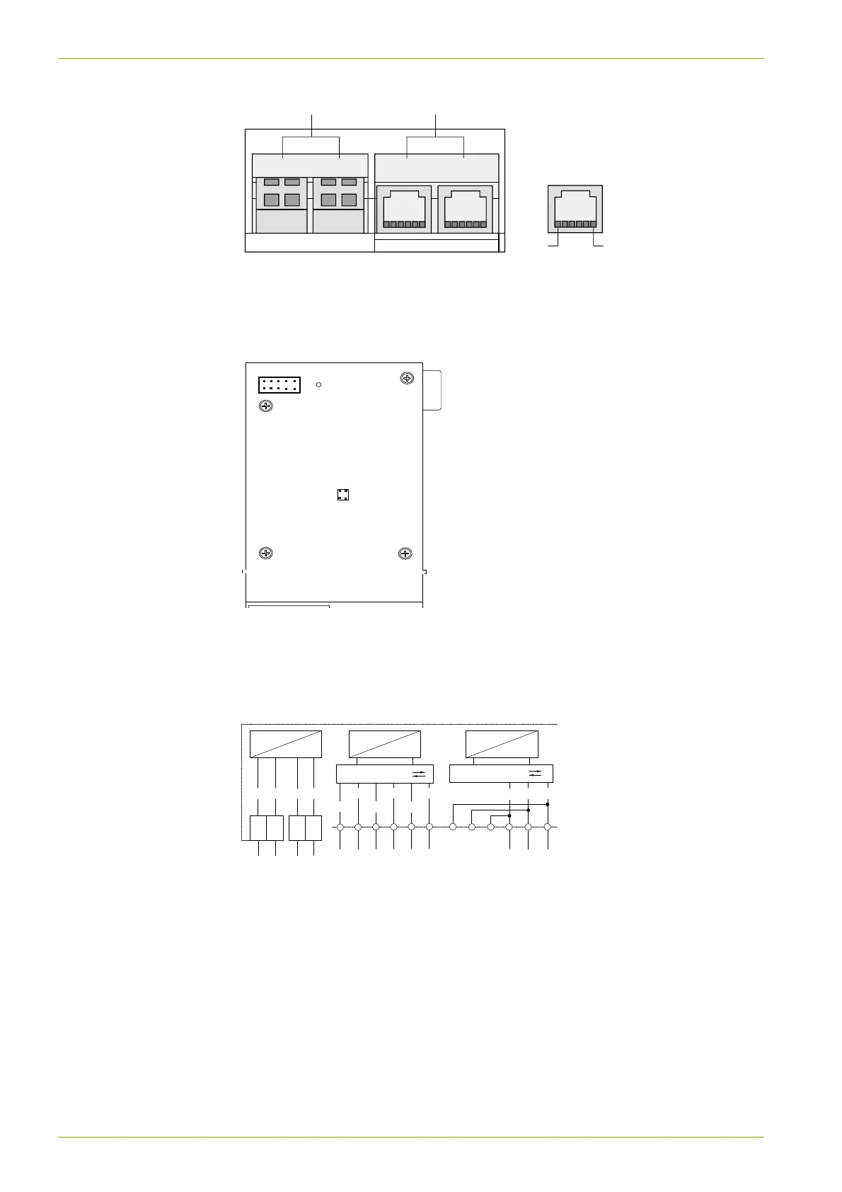
S01 S02 RS485 RS485
Pulse inputs
(if present)
Communication
interfaces
CU-B2
1
6
Pin allocation RS485:
1 c (ground)
2 a (data a)
3 b (data b)
4 b
5 a
6 c
Fig. 3 External connections communication unit CU-B2
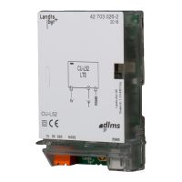
Connections to meter
Type: 10-pin and 4-pin p.c.b. connector
Fig. 4 Internal connections at rear of communication unit CU-Bx
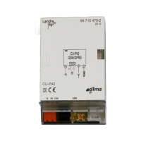
1.2.5 Connection diagram
DC
DC
+
-
+ - + -
2320 21 22
DC
DC
DC
DC
+
-
65
DSR
RxD
RS485
5432
a
b
4
3
DTR
GND
21
TxD
CTS
RS232
6
1
c
Fig. 5 Connection diagram communication unit CU-B1/B4
CTS: Clear To Send
TxD: Transmitted Data
GND: Signal ground
DTR: Data Terminal Ready
RxD: Received Data
DSR: Data Set Ready
In the transparent RS232 interface, connections CTS, DTR and DSR are
connected to ground (GND) by the software.
4-pin connector
10-pin connector