24/30 Installation and commissioning
© Landis+Gyr D000011142 en k – E65C CU-B1, B2, B4 – User Manual
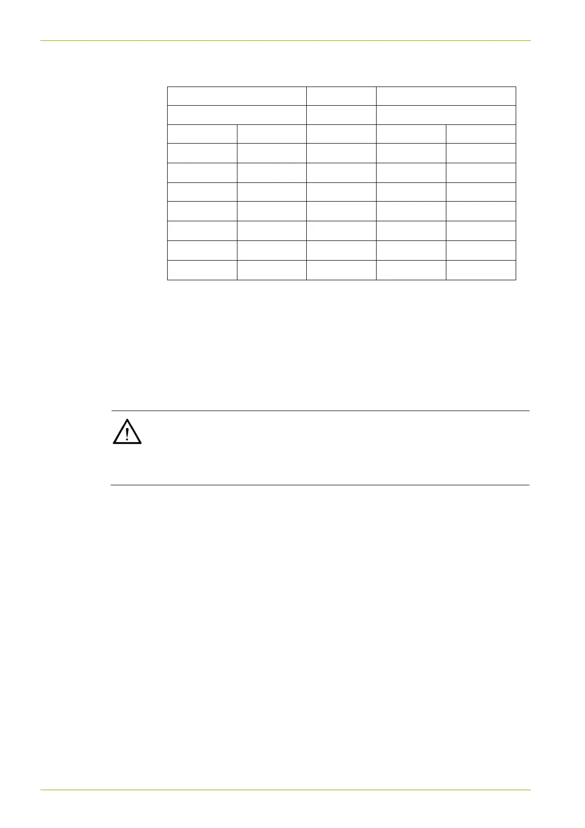
Connection to modem
Data receiver Meter with CU-Bx
DB-9 socket RJ12 socket
Pin Signal Direction Pin Signal
8 CTS
1 CTS
3 RxD
2 TxD
5 GND 3 GND
4 DTR
4 DTR
7 RTS 1)
2 TxD
5 RxD
6 DSR
6 DSR
1) The modem must be configured so that RTS need not be used.
RTS at the DB-9 socket should be connected to DTR at the RJ12
socket, so that the RTS input to the modem has a defined potential.
RTS must also be set to "logic 1".
5.4.4 Connecting the RS485 interface
Connect the RS485 interface according to the diagram on the faceplate.
External wiring of RS485
In order to function correctly, all 3 wires (data a, data b and Common GND)
must be connected. RS485 operation with only 2 wires (without Common
GND) is forbidden as the RS485 interface may not function correctly or be
damaged.