8
LANDMANN
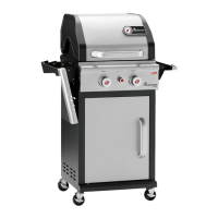
3. Guide the Landmann panel (6) over the standing leg
(5) from below.
4. Tilt the Landmann panel (6) upwards slightly and
screw the standing leg (5) to the base (2) by using an
M6 x 35 mm bolt (s1) and an M6 nut (n1).
5. Secure the Landmann panel (6) to the standing leg (5)
by using two M5 x 35 mm bolts (s4).
42
7
7
8
8
n2
w1
w3
7
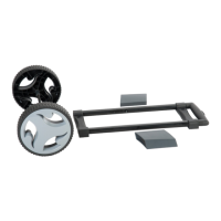
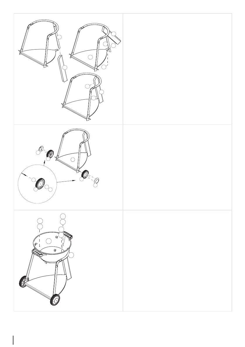
6. Attach the rst wheel (7) to the axle on the base (2) in
the following order:
– Slide a Ø 9/16 mm washer (w1) onto the axle.
– Slide a wheel (7) onto the axle.
– Slide a Ø 9/20 mm washer (w3) onto the axle.
– Attach a self-locking M8 nut (n2).
7. Assemble the other wheel (7) using the same method.
8. Attach the wheel caps (8) to the wheels (7).
The two pins on the wheel caps stick into the holes in
the wheels.
9. Position the re bowl (9) on the U-section (4) and
screw the two parts in place.
When doing this use three M5 x 10 mm bolts (s2) and
Ø 6.5/20 mm washers (w2).