INVERTER OPERATION
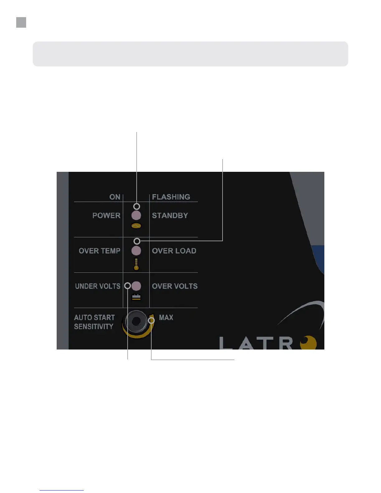
LED Indicators
Standby/Power (Green LED)
This LED ashes when in standby mode
(i.e. no loads connected). When a load is
applied the LED will illuminate continuously to
indicate that 240V a.c. is being supplied.
Over temp/Over load (Red LED)
If the internal temperature exceeds safe operating limits of
the components for more than ve seconds, the inverter
will shut down in over temp with this LED on continuously.
Turn the ON/OFF switch o and allow 5 minutes for the
inverter to cool, then turn it back on. If the applied load
demands more current than the inverter can safely supply
for more than 5 seconds, the inverter will shutdown in over
load and this LED will ash.
Auto Start Sensitivity Adjustment
The screwdriver adjustment slot permits the operator to
adjust sensitivity between 0- 20W. Due to lengthy 240V a.c.
cables the inverter may sense fake loads. To combat this,
turn the control clockwise. Alternatively turning the control
in the opposite direction increases sensitivity. Turning the
control fully anti-clockwise will disable the auto start feature
and the inverter will remain constantly ON.
Undervolts/Overvolts (Red LED)
In order to protect the battery the inverter will
shutdown after 5 seconds if the battery voltage
falls below its limit, (undervolts), or exceeds
the maximum, (overvolts), as specied in the
specications table on page 22. For undervolts
the LED will remain on continuous, while for an
overvolts situation the LED will continue to ash.
10