Do you have a question about the LAUMAS WLIGHT and is the answer not in the manual?
Provides explanations for warning symbols and reading instructions.
Guidelines for operating the weighing instrument safely and correctly, including installation advice.
Advice on installing load cells, including cable management and structure stability.
Ensures proper placement, alignment, and stability for load cells on rigid structures.
Covers cell cable connection, protection against water, and mechanical restraints for pipes.
Addresses vibration, wind, and welding procedures near load cells to prevent damage.
Checks load cell response signal in mV, confirming basic functionality.
Guides on using multimeters for load cell electrical checks: input resistance, insulation, and voltage.
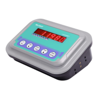
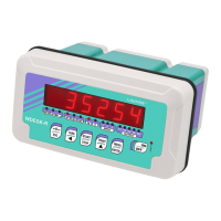
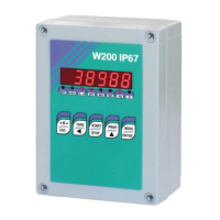
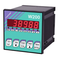
Details on instrument dimensions, display type, keyboard, signaling LEDs, and protection rating.
Information on RS232 port, supported protocols, and power supply requirements.
Covers power, load cells, linearity, thermal drift, AD converter, max divisions, and display range.
Specifies operating temperature, humidity, baud rates, and serial port capabilities.
Information on connecting load cells, supported counts, and 4-wire configurations.
Details pin assignments for power supply, load cell (D1 Female), and RS232 serial port (D4 Male).
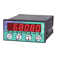
Explains short press, long press, and menu navigation for each key (Tare, Start/Stop, Print, Menu/Enter).
Describes the meaning of different LED lights (NET, →0+, stability, units) on the instrument.
Describes the display sequence upon turning the instrument on, including model and version.
Verifying existing calibration status and load cell connections before proceeding.
Steps for theoretical and real calibration based on device status and load cell data.
How to access and modify instrument parameters using MENU/ENTER and ESC keys.
Configuring FS-LED (Full Scale) and SEnSi (Sensitivity) parameters for load cell calibration.
Adjusting the display resolution or minimum weight increment (division).
Setting the upper limit for weight display before showing overflow indication.
Procedure to set the current weight of the empty system to zero.
Entering an estimated zero value when automatic zeroing is not possible due to product residue.
Using sample weights to calibrate the instrument and correct displayed values.
Performing multi-point linearization for improved accuracy across the weight range.
Adjusting filter values (0-9) to achieve a stable weight reading by reducing fluctuations.
Setting the anti-peak filter to remove transient weight spikes up to 1 second.
Defining the threshold for resettable weight changes via external contact or protocol.
Configuring power-on zeroing and zero tracking to maintain accuracy.
Lists and defines the selectable units for weight display (kg, g, lbs, etc.).
Activating semi-automatic and preset tare operations for net weight calculations.
Steps for setting the instrument to display net weight using the TARE key.
Setting a fixed tare value to subtract from the gross weight manually.
Procedure to zero the scale for small weight changes within the O SEE limit.
Enabling and using the peak function via START/STOP to capture maximum weight.
Choosing between RS232, Modbus, or ASCII protocols for data transmission.
Setting baud rate, address, transmission frequency, and other communication parameters.
Wiring diagram showing pin assignments for connecting the instrument via RS232 to a PC.
Method for connecting RS485 output to an RS232 input for one-way communication.
Running the millivolt test to check load cell signals and response.
Details on NiMH battery type, charging, low battery indication, and operating times.
Configuring the display to enter energy saving mode after inactivity.
Procedure for setting the internal date and time accurately.
Accessing model, software, hardware, and serial number information.
How to count items added or removed from the scale for inventory or batching.
Information on how the piece count, average unit weight, and total weight are displayed.
Choosing between Base operations, Piece Counter, and Totalizer modes.
Setting up fast manual, normal manual, or automatic totalization with hold and stability options.
Understanding how total weight is presented in different totalizer modes (E, b, A).
Important notes on totalization, clearing data, and blocking weight display.
Detailed explanations of common alarm codes (ErCEL, Er OL, etc.) and their causes.
Error codes specific to communication protocols like Modbus, ASCII, and RIP.
Examples of print formats for basic weighing, piece counter, and totalizer modes.
Protocol for transmitting weight data at high update rates (up to 300 strings/sec).
Structure and content of transmitted data strings for PC/PLC communication.
Protocol for sending weight data to compatible remote displays (RIP series).
Format of data sent to remote displays, including net/gross, prompts, and error handling.
General information and definitions for ASCII communication, including status and control characters.
PC commands for retrieving weight and peak values using ASCII strings.
PC commands for semi-automatic zero and switching between gross/net weight.
PC command to switch the instrument from net to gross weight display.
PC command to perform tare zero setting via ASCII communication.
PC command for performing real calibration with sample weights using ASCII.
Method for calculating the checksum for ASCII communication data integrity.
Basics of Modbus-RTU, data format, and supported functions for register management.
Explanation of reading and writing programmable registers using Modbus-RTU.
Query and response structure for reading data registers (e.g., Function 3).
Query and response structure for writing data registers (e.g., Function 16).
Procedures for CRC checks, exceptional responses, and interpreting error codes.
Table detailing registers, their descriptions, EEPROM saving, and access types (R/W).
Explanation of each bit's meaning within the status register for system state monitoring.
Configuration options for weight divisions and measurement units for display and calculation.
List of commands for functions like tare, zeroing, keypad locking, and saving data.
Commands for saving sample weight and initiating real calibration via the command register.
Demonstrates sending multiple register write commands and expected instrument response.
Demonstrates sending multiple register read commands and expected instrument response.
Procedures for locking, unlocking, and setting passwords for menu access.
Warnings and procedures for data deletion and program selection requiring technical assistance.
Methods to lock the keypad and/or display for security or accidental input prevention.
| Category | Accessories |
|---|---|
| Type | Weight indicator |
| Power supply | 12-24 V DC |
| Housing | ABS |
| Protection degree | IP65 |
| Display | LED |
| Digit height | 14 mm |
| Serial ports | RS232/RS485 |
| Operating temperature | -10..+40 °C |
| Storage Temperature | -20 to +70 °C |