LAUNCH 440(440W) 455(455W) Installation Manual
29
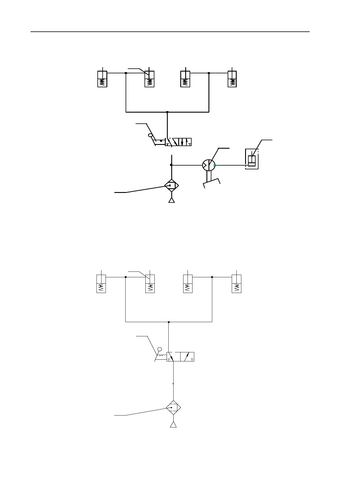
TLT440W, TLT455W Diagram of Pneumatic system:
1
3
X Y
4
5
P
P
S R
B A
2
1.AirSource2.AirControlValve
3.AirCylinder
4PneumaticPump5Cylinder
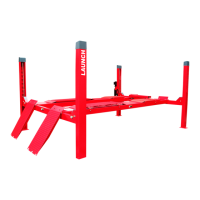
TLT440, TLT455 Diagram of Pneumatic system:
1
3
P
R
A
2
P
1.Air Source 2. Air Control Valve 3. Air Cylinder
www.diagtools.eu, Pernavas 43A, Riga, Latvia, LV-1009, +37129416069, info@diagtools.eu