LAUNCH 440(440W) 455(455W) Installation Manual
7
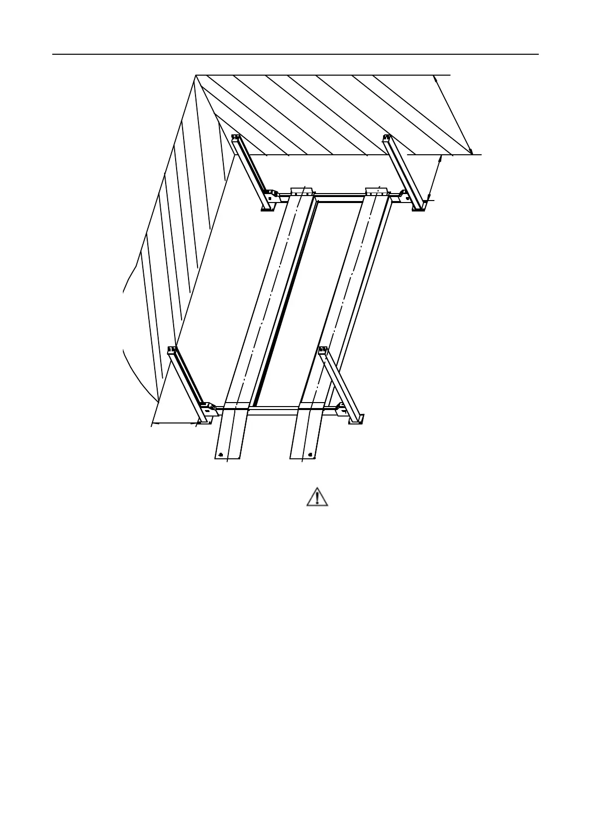
≥ 1m
≥
1
m
≥
4
m
Fig.5
5.2.2 Base Plate layout
The bay layout is shown in Fig. 6.
l With total width as the basis, draw two parallel lines (#1
and #2) on the concrete slab, with the error within
3mm.
l Confirm the position of the power column near the
power source and mark the overall width and length so
that the position of 3 other columns can be confirmed.
l Draw a diagonal line to show a triangle. The location
of the columns can be set with reference.
Note:
l All the dimensions are based on the external
border of the base plate.
l Ensure the overall error is controlled within 6mm.
In this way, the difficulties in the final assembly, or
early wear or non-alignment of the lift can be
eliminated.
l The marking and layout is very important. If it is
inaccurate, there will be problems during the final
assembly and operation.
www.diagtools.eu, Pernavas 43A, Riga, Latvia, LV-1009, +37129416069, info@diagtools.eu