LAUNCH 440(440W) 455(455W) Installation Manual
4
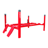
2.2 Working Principle
l Lifting mechanism: The hydraulic cylinder is
located below the cylinder runway. When the
hydraulic oil enters the front cavity of the cylinder,
the piston moves backward so that the left and
right runways will be moved upward at the force of
the cables.
l Support Mechanism: The cylinder runway and the
right runway are installed on the cross tubes as a
part of the supporting platform. When the
vehicle is driven onto the runways, the wheels
should be positioned on the central line of the
runways. The rolling jack can be placed at a
suitable position between the runways. Adapters
of different length can be used according to the
height of the chassis.
l Balance mechanism: 4 synchronization cables
work together to keep the balance while lowering
and lifting. The threaded end of the cable is
fastened on top of the columns and the cables
should be adjusted for same tension.
l Safety protection mechanism: 4 locking latch
plates are located in the back of columns. The
safety locking latches and slack cable devices are
located in the ends of cross tubes. While the
runway goes up, the safety locking latch rises
together against the locking latch plate at the force
of the spring in the air cylinder. When the
runway stops, the safety locking latch will insert
into the slot of latch plate to prevent the runway
from falling. For lowering the lift, when the
locking latches rest on the plates, it must be
raised enough for all 4 latches to clear the latch
plates slots inside the columns. Actuate the air
control valve to disengage all 4 locking latches
and push the lowering handle on the power unit to
lower the lift.
l Cable slack or broken protection: During the
raising and lowering the lift, the equal tension
cables will press the slack cable roller to
disengage the latches. If the cable is slack or
breaks, the slack cable device will insert into the
slot of locking latch plate to ensure the safety.
(Fig. 3)
l Safe travel distance: The safety locking latch is
kept active from the height of 270mm to 1900mm.
l Leveling preset: 4 adjustment nuts at top plates of
the columns can be adjusted to level the runways.
(Fig. 4).
l Rolling jack mechanism (440W) : The jack cylinder
is located in the scissor lift. When the hydraulic
oil reaches the lower cavity of the cylinder, the
piston will move forward, forcing the shaft to push
the scissor table upward.
l There is a locking latch in the rolling jack (440W) :
When the jack goes up high enough, the locking
latch will be engaged. To lower the rolling jack,
raise jack and release locking latch by lifting
release handle, and then press lowering valve.
www.diagtools.eu, Pernavas 43A, Riga, Latvia, LV-1009, +37129416069, info@diagtools.eu