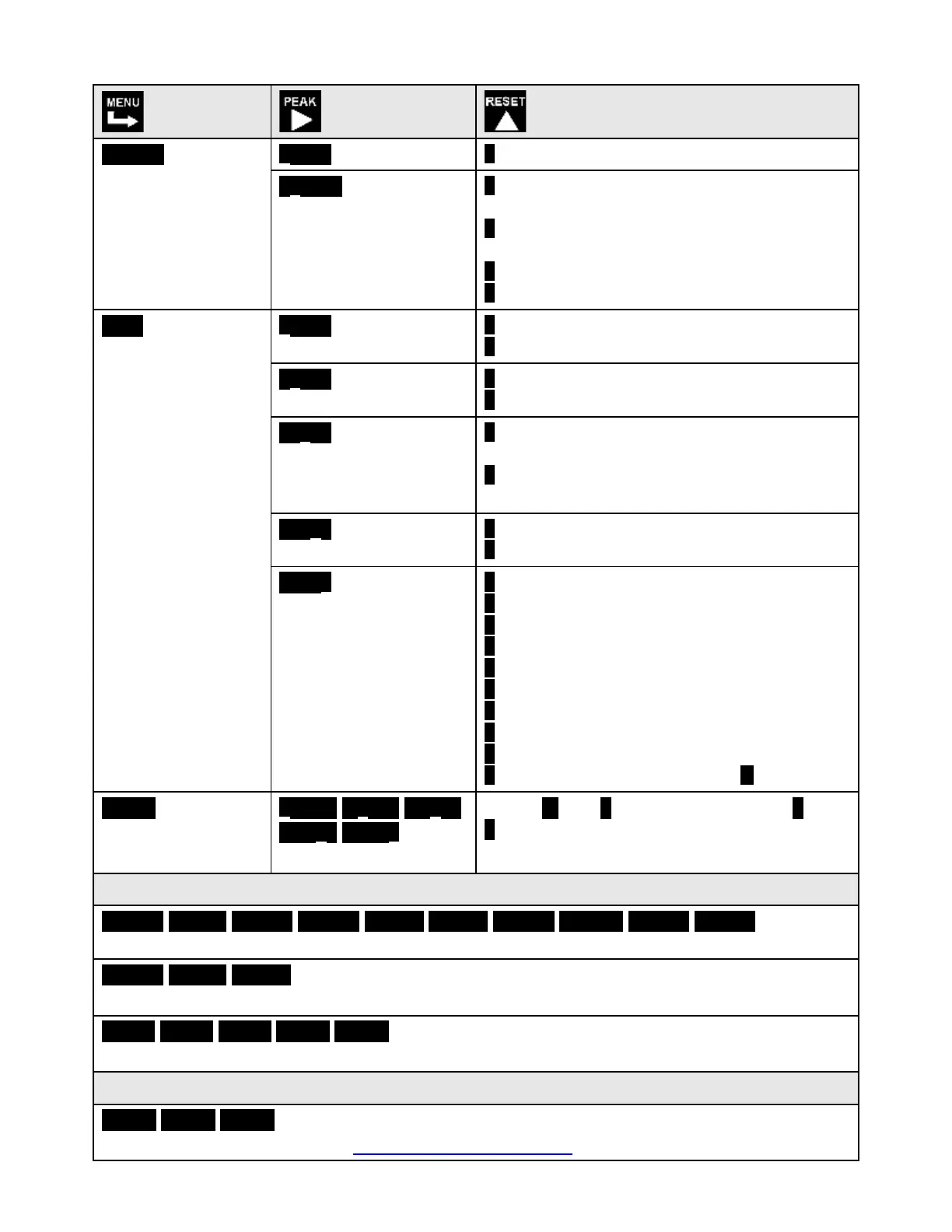
ConFG
Meter
Configuration
00 _ _0
Operation of front
panel PEAK button
and rear connector for
Peak or Valley Display
0 Peak Display. Also selects “Peak” in
“Peak or Valley” at rear connector.
1 Valley Display. Also selects “Valley” in
“Peak or Valley” at rear connector.
2 Peak (1st push), Valley (2nd push)
3 Front panel Tare
0 Unfiltered output
1 Filtered output
00000
Peak & Valley filtering
0 Unfiltered Peak & Valley
1 Filtered Peak & Valley
0 Display batch average of every 16 read-
ings. 3.5 updates at 60 Hz, 3.0 at 50 Hz.
1 Display per input signal filter setting
below
00000 Adaptive filter
threshold for all filters
0 Low adaptive filter threshold level
1 High adaptive filter threshold level
00000
Input signal filter
setting
Can be applied to dis-
play, setpoint, analog
output, data output.
0 Autofilter. Time constant set by meter.
1 Batch average of 16 readings
2 Moving average, 0.08 sec time constant.
3 Moving average, 0.15 sec time constant.
4 Moving average, 0.3 sec time constant.
5 Moving average, 0.6 sec time constant.
6 Moving average, 1.2 sec time constant.
7 Moving average, 2.4 sec time constant.
8 Moving average, 4.8 sec time constant.
9 Moving average, 9.6 sec. A Unfiltered
0.0000 0.0000 0.0000
0.0000 0.0000
Select digit to flash.
Select -9 thru 9 for flashing first digit, 0 thru
9 for other flashing digits. Use offset for
display in Rankine or Kelvin.
Option board dependent menu items
ALSEt. ALS34 dEU1H dEU2H dEU1b dEU2b dEU3H DEU4H DEU3b DEU4b
Menu items related to alarm setup if a relay board is detected. Please see Section16.
AnSEt. An Lo. An Hi..
Menu items related to analog output if detected. Please see Section 17.
SEr 1. SEr 2. SEr 3. SEr 4. _Addr
Menu items related to communications if detected. Please see Section 18.
Loc 1. Loc 2. Loc 3.
Menu items used to enable or lock out (hide) menu items. Please see Section 9.
 Loading...