- 34 -
15. RTD & RESISTANCE INPUT
The standard RTD and resistance signal conditioner board are jumper selectable for four RTD
types (DIN 100Ω platinum, ANSI 100Ω platinum, 120Ω nickel, 10Ω copper) and five resistance
ranges (from 20.000Ω to 200.00 kΩ). Fixed 2Ω, 2 MΩ or 20 MΩ resistance ranges require a
factory modified signal conditioner board where other ranges are no longer jumper selectable.
All ranges are factory calibrated with calibration factors stored in EEPROM on the signal
conditioner board. The meter software recognizes the board and will bring up the appropriate
menu items for it; however, it does not recognize the jumper settings. With RTDs, display in °C
or °F and resolution of 1°, 0.1° or 0.01° are user programmable.
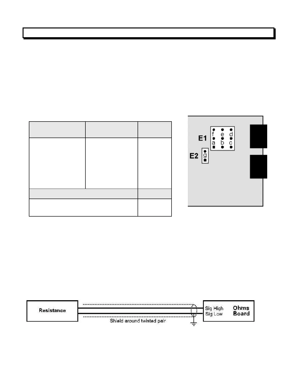
SIGNAL CONDITIONER BOARD SETUP VIA JUMPERS
1. Jumpers are installed on pins bridging letters.
2. Use 2.5 mm (0.1") jumpers.
3. Store unused jumpers on one pin so that one side is not connected.
SCALE & OFFSET SETUP
Scale is normally set to 1.0000. Scale can be used as an RTD resistance multiplier when the
actual resistance is other than nominal at 0°C. For example, if the resistance of a Pt100 RTD is
measured as 99.04 ohms at 0°C, you can apply a scale factor of 100 / 99.04 = 1.0097.
Offset allow the reading in degrees or ohms to be increased or decreased by a fixed amount.
SIGNAL SHIELDING
Shielding for noise reduction
Ranges of 200 kΩ and above are susceptible to signal noise. To minimize noise pickup, the
input signal wiring should utilize a shielded twisted pair, and the shield should be connected to
signal low and earth ground at the meter, as illustrated.
 Loading...