- 24 -
13. AC TRUE RMS VOLTS & AMPS INPUT
AC voltage or current measurement utilizes
the True RMS signal conditioner board which
uses precision circuitry to compute the root-
mean-square of complex waveforms from 10
Hz to 10 kHz. Accurate measurements are
obtained with spikes up to 3 times the
maximum of each range. The input can be
AC coupled to read only the AC component,
such as ripple on a power supply, or DC
coupled to read AC plus DC. The board
needs to be configured via jumpers for the
desired voltage or current range, and for AC
or DC coupling. All signal ranges are factory
calibrated with calibration factors stored in
EEPROM. The meter software recognizes
the board and will bring up the appropriate
menu items for it; but it does not recognize
the jumper settings. These need to be set manually. Please see further manual sections for relay
output, analog output, communications, and transducer excitation output.
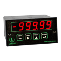
RANGE SELECTION VIA JUMPERS
1. Letters indicate jumper position. Jumpers are
installed on pins adjacent to letters.
2. Use 2.5 mm (0.1") jumpers.
3. Store spare jumpers on unused jumper post.
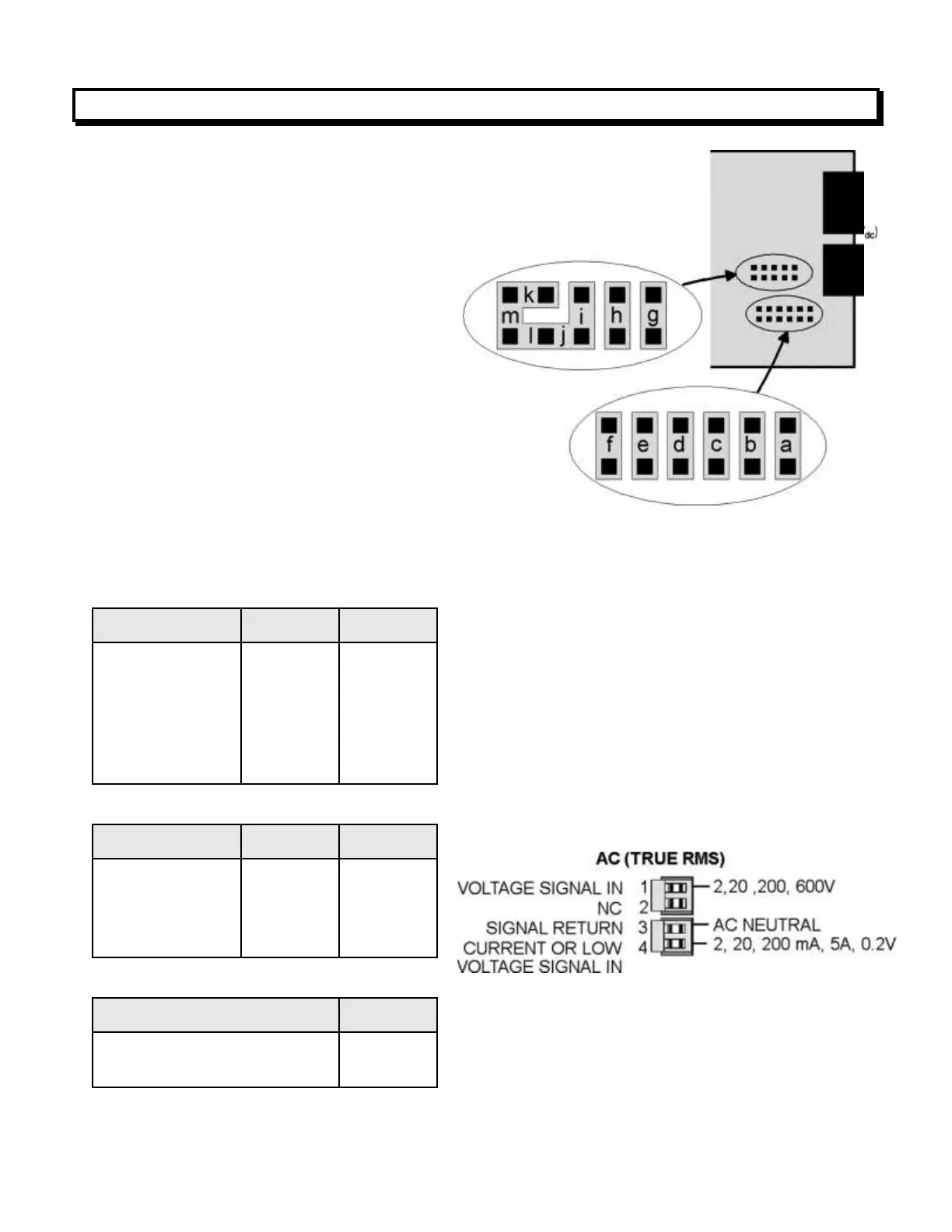
SIGNAL CONNECTIONS
The RMS signal is applied to the signal conditioner
board at P5, which is on the right when the meter
is viewed from the back.
 Loading...