10
Align the holes and assemble the retainer
1 and retainer 2 onto the clamps. Ensure
the direction of the retainers as shown
in the following picture. Secure the
connection with M6x16 bolts, washers
and nuts.
Secure the log clamps on the armguards
with star knobs and flat washers.
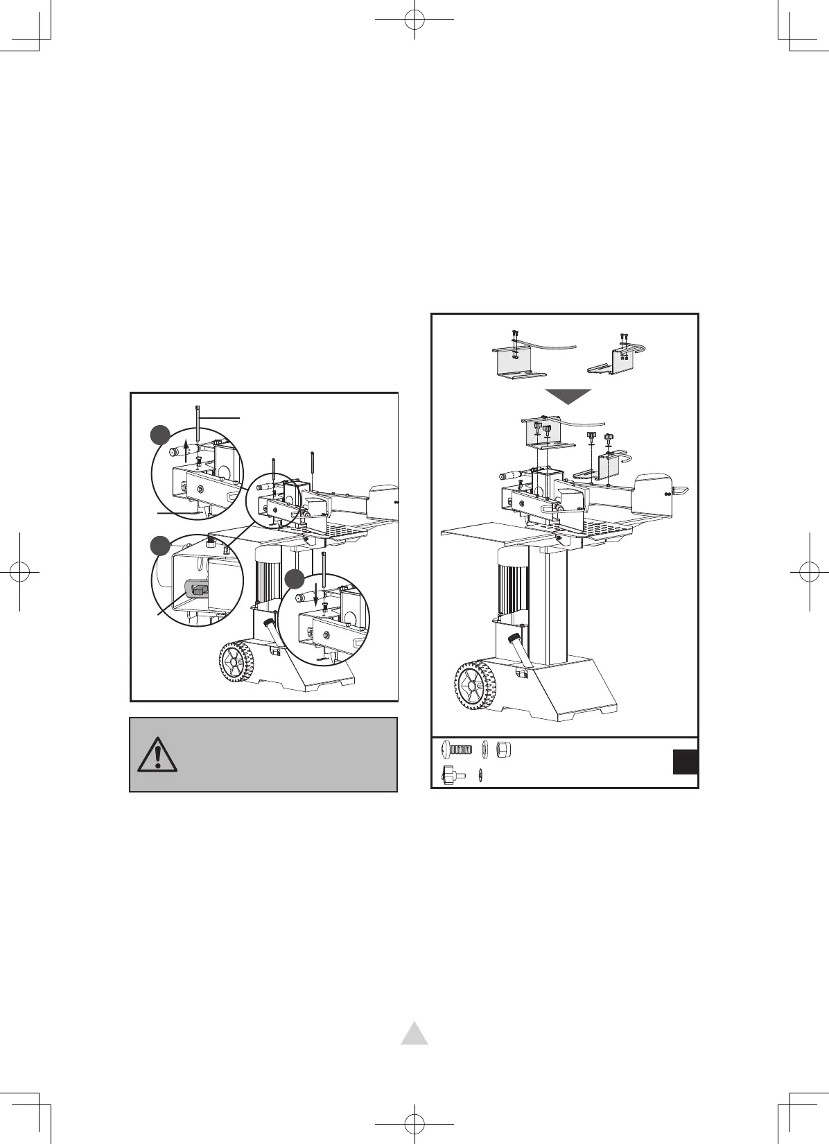
Pull Spring Pin (A) to remove the Lock
Pin (B). Apply a thin coat of grease
to both surfaces of the Control Lever
Guard as illustrated. Insert the Control
Lever and Guard Assy and make sure
the Control Lever End goes into the slot
of Connection Bracket (C). Lock the
Control Lever and Guard Assy. down
with the Lock Pin (B) and Spring Pin
(A). Follow the same steps to install the
other Control Lever and Guard Assy on
the other side.
Control Lever Adjustable Log Holder
1
2
3
A
B
C
Check both sides after
assembly. The control levers
must be placed in the slots
of connection brackets.
M6
×
16
×
4
B
×
4