mc²36 xp Installation & Service Guide Version: 1.0/1 45/59
6. Service Procedures
6.7 Bayserver & Gateserver Switch Settings
Within each channel and central bay, individual panels and displays connect to an Ethernet Bayserver or
Gateserver (mounted inside the frame). In both cases, the servers have a number of switches which you may
need to adjust if you are replacing a TFT display.
Switch Settings
The switch settings are used as follows.
·
S1 DIP Switch 1 (One PSU only) – set to ON if only one PSU is connected.
·
S1 DIP Switch 2 (PSU Connected) – set to ON if a PSU block is installed in the bay.
·
S1 DIP Switch 4 (GUI Mode) – sets the GUI mode: ON = Central GUI, OFF = Channel Display.
·
S1 DIP Switch 3, 5, 6, 7, 8 – are unused and should be set to OFF.
·
SW1 Rotary Switch (Address) – sets the bay index, counted from left to right (in two's) as viewed from
the front of the frame starting at 0.
Example Configuration
Start by setting the S1 DIP Switches 1 and 2 to the correct positions.
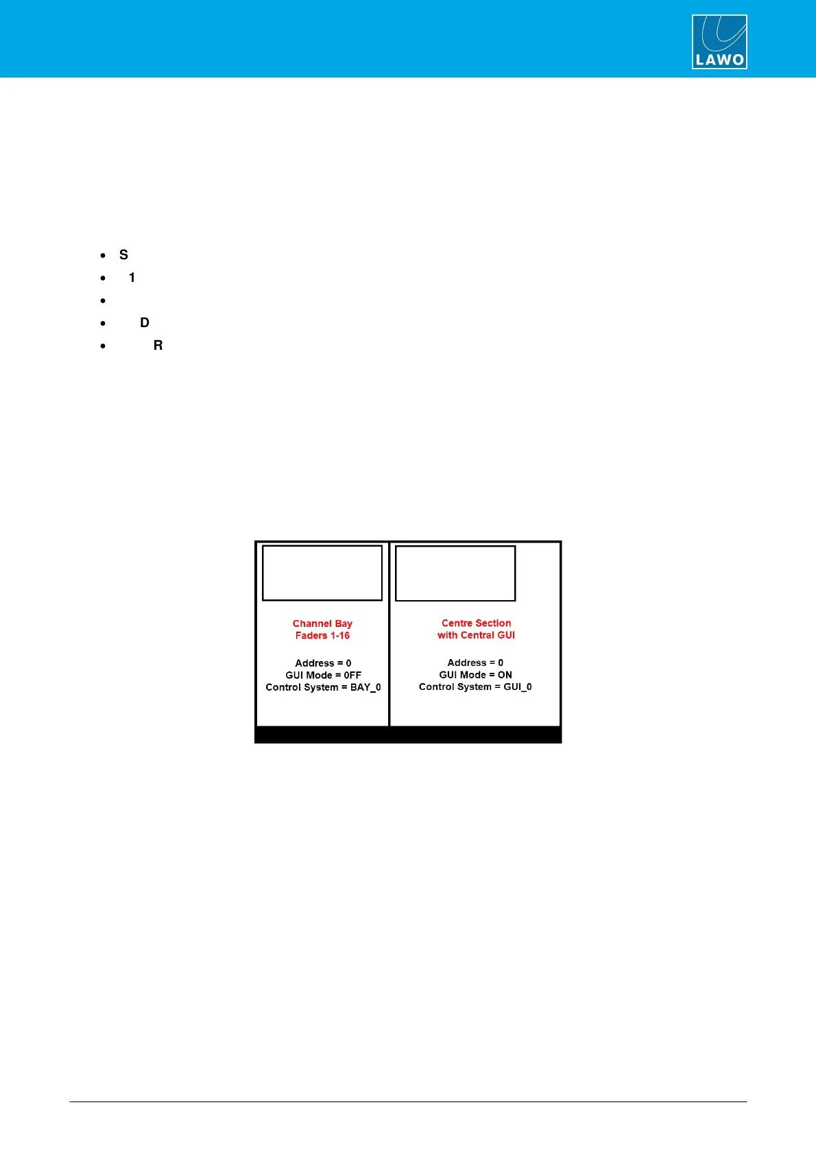
If the server is fitted to a central bay, set the S1 DIP Switch 4 (GUI Mode) to ON and the SW1 Rotary Switch
(Address) to 0.
If the server is fitted to a channel bay, then set the S1 DIP Switch 4 (GUI Mode) to OFF and the SW1 Rotary
Switch (Address) to the correct index number (0 or 2).
The example below shows the correct settings for a 32-fader frame: