3
lci1.com 574-537-8900 Rev: 11.05.20
Floë 636 Integrated
Water Drainage System
Installation and Owner’s Manual
(For Aftermarket Applications)
CCD-0003522
Fig.3
4. Cut 2” o the air line to t onto the end of the elbow and
then onto one end of the shuto valve. (Fig.3).
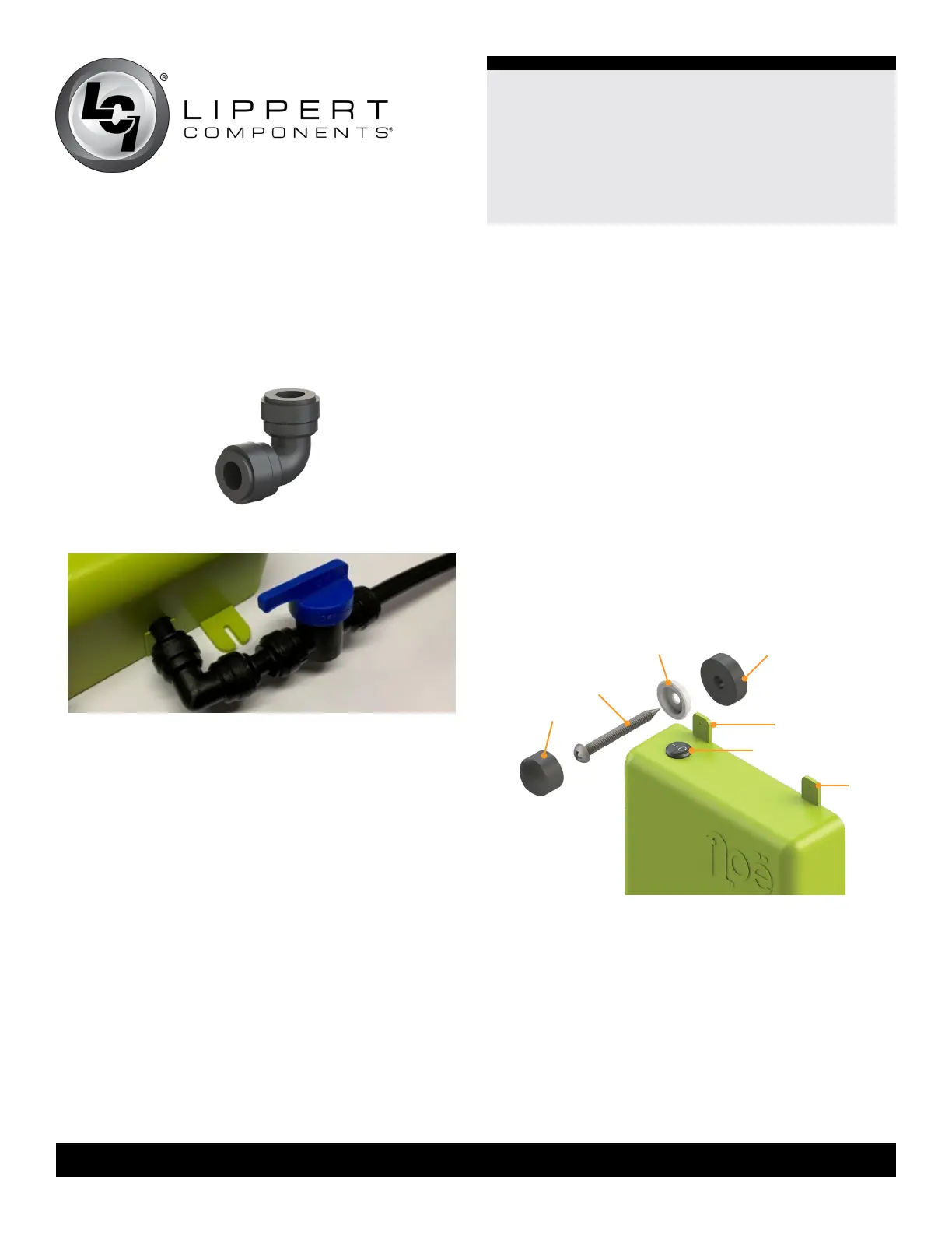
On/Off button
tab
tab
screw
cap
white retainer
washer
screw
anti-vibration
washer
Fig.4
2. The shuto valve is a second safety valve and should be
used as a backup to the rst one-way safety valve built into
the tee.
3. If the air line needs to be installed horizontally to avoid
kinking, t the elbow joint (Fig.2) onto the air line stump on
the Floë box.
NOTE: The longer air line will be connected to the shutoff
valve after the box is installed on the wall.
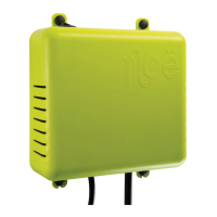
Attach Box To Wall
1. Locate a secure surface for installing the Floë box within
13’ of a 12V power supply and within 13’ of the water
supply line from the water tank or outside the wall.
NOTE: The On/Off button on top (Fig.4) must be accessible
or the in-line DC switch will need to be used for operation.
NOTE: Toggle bolts or, if necessary, dry wall rawl plugs
can be used if installing the Floë box on drywall.
NOTE: It is not recommended to install the Floë unit on
an outside wall since it could create bumps on the outside
finish of RVs.
NOTE: Floë should be installed upright, not flat. Try to use a
corner, door jamb or cupboard to keep Floë straight and level.
Connect Tee Fittings And Air Line
1. Make sure to switch o the pump and any other
electrical devices. Locate the hose leading from the fresh
water tank to the lter and pump.
2. Using pipe cutters or shears, cut through the hose near
the water tank.
NOTE: Cut the hose 2” from the water tank, or as close as
possible, but still allow for fitting of barbed connector. Do
not cut the hose in a section that is curved. A curve puts
undue pressure on joints and can cause air leaks.
Fig.2
2. Use an awl or punch to make indentations to start the
screws, beginning with the screws on the bottom of the
box.
3. Install white retainer washers on the screws and insert
screws through holes in the box tabs (Fig.4).
4. Then place anti-vibration washers on screws (Fig.4) and
fasten the box to the wall. Leave box loose to allow for
vertical adjustment.
5. Insert the top screws and washers into the tabs on the
Floë box and, after making nal adjustments, attach the
box to the wall.
6. Tighten screws until the white retainer washers can no
longer move. Do not overtighten. Overtightening could
crack the green box tab.
7. Snap on black caps over the retainers on the screws.
 Loading...