4
lci1.com 574-537-8900 Rev: 11.05.20
Floë 636 Integrated
Water Drainage System
Installation and Owner’s Manual
(For Aftermarket Applications)
CCD-0003522
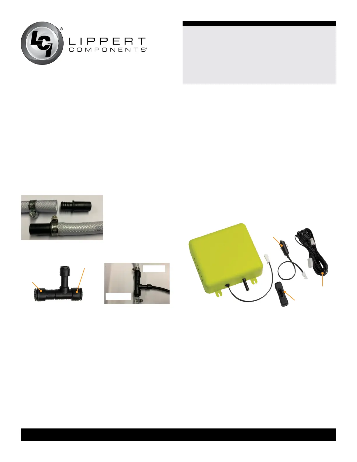
Connect To 12V DC Power Supply
1. The supplied 13’ DC wire has male and female
connectors and a fuse (Fig.8). Connect one end of the
connector to the Floë box and the other end to a power
supply.
NOTE: The white connector can also be removed to create
bare wires on the end. Then it can be fitted to a fuse box or
fitted directly to the battery using ring terminals.
NOTE: The fused wire is for a red/positive connection and
can also be fitted onto an optional in-line switch included
with the kit (Fig.8).
2. The 15A power plug can be tted to a cigar/cigarette
lighter socket (Fig.8). Connect one end to the connector on
the Floë box and the other end to a socket.
3. Use a cable tie to hold together excess cord.
Fig.5
Fig.6 Fig.7
13’ DC Wire
power plug
in-line switch
short side
to pump
long side
to tank
Fig.8
NOTE: Use a cloth to mop up excess water from the cut
water line.
3. Insert teeth end of the barbed connector onto the end of
the hose (Fig.5).
4. Slide hose clamp over end and tighten (Fig.5).
5. Repeat process for other side of the cut hose.
6. Fit the ends of the ½” air line tee rmly into the
connectors, utilizing the tee’s push-t connections (Fig.6).
The long side of the tee should extend toward the tank while
the shorter side should extend toward the pump (Figs.6, 7).
NOTE: If larger or smaller pipes are used, adapters can
be purchased from hardware stores. Additionally, the tee
can also be fitted to rigid plastic and copper pipes without
adding barbed connectors.
NOTE: There are two one-way valves built into the tee.
One is to stop water escaping back up into the Floë unit.
The other is to stop air traveling back into the water tank,
where it would escape out of the tank air vent.
7. Measure the distance from the air line shuto valve on
the Floë box to the tee installed on the water line.
8. Cut air line to length, leaving at least an extra half inch to
an inch of air line to slide into the connectors.
Test For Air Leaks
At this point Floë has been dry fit. Test that all joints
leading up to the main water line are fitted correctly without
air leaks. Locate the main water line tee and remove the
barbed connector from the short end of the tee leading
to the faucets, NOT the water tank long end. The barbed
connector is removed by pulling back on the collar of the
tee that holds the barbs in place.
Place a finger into the tee to seal this end and switch on
Floë. Floë should be tricked into stopping at 15 psi. If Floë
stops, then the joints leading to the water system are fine.
If Floë doesn’t stop, then remove, wet and reseat the air
line into the connectors leading back to Floë. It is essential
there is a good seal on the open end of the tee to allow this
test to work.
To Tank
To Pump
 Loading...