F264 0.1
F265 0.1
F266 0.1
F267 0.1
F268 0.0
F269 1
F270 0.0
F271 0.0
F272 0.0
F273 0.0
F274 0.0
F275 0.0
F287 60.0
F288 0.0
F289 0.0
F290 0.0
F291 0.0
F292 0.0
F293 0.0
F294 0.0
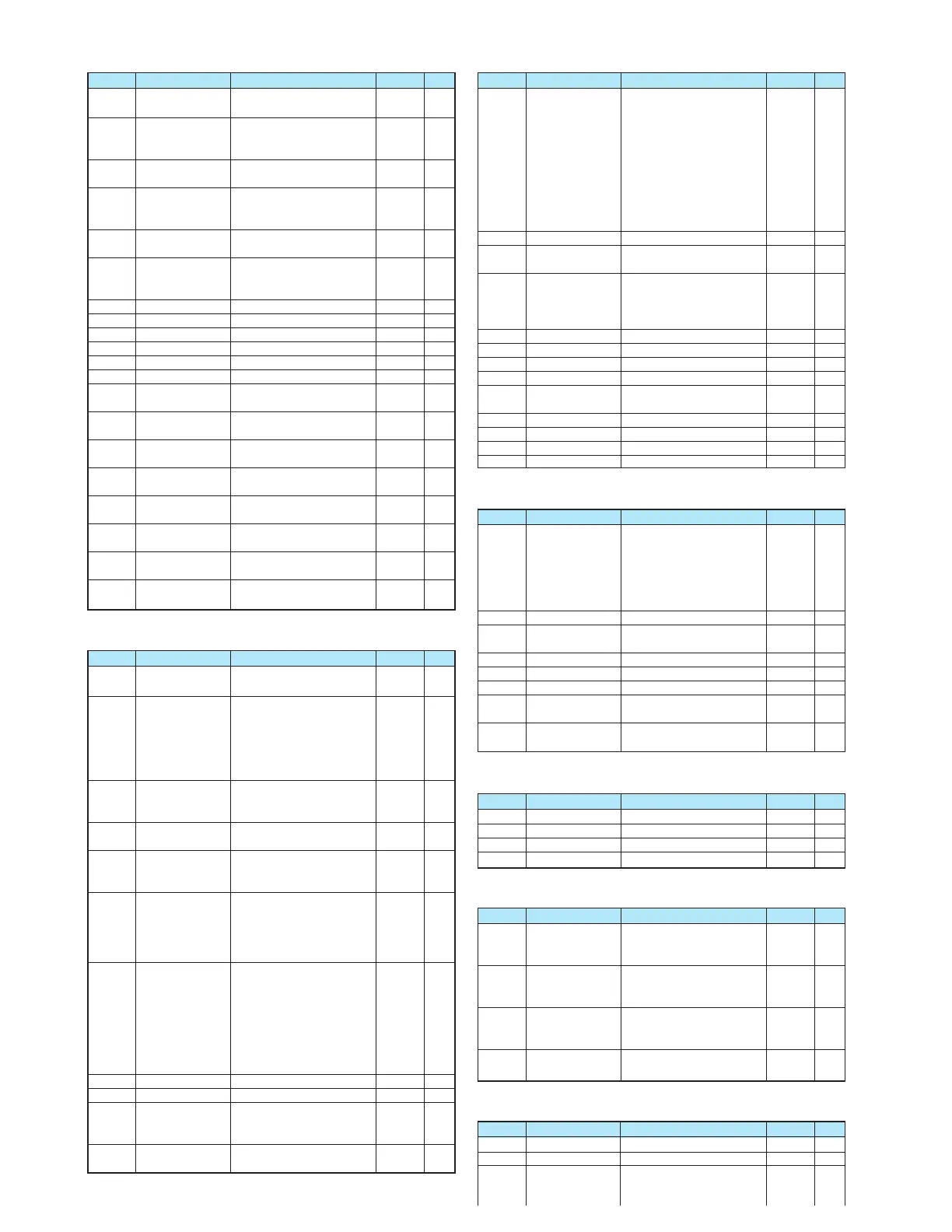
● Operation Mode Parameters
F300 4.0
F301 0
F302 0
F303 0
F304 0
F305 1
F307 3
F308 *1
F309 *1
F311 0
F312 1
F316 1
F320 0
F323 10
F342 0
F343 3.0
F344 0.05
F345 3.0
F346 0.10
F359 0
F360 0
F362 0.30
F363 0.20
F366 0.00
● Torque Boost Parameters 1
F400 0
F401 *1
F402 *1
F415 *1
F416 *1
F417 *1
F418 40
F419 20
● Input/Output Parameters 2
F470 128
F471 128
F472 128
F473 128
● Torque Boost Parameters 2
F480 100
F485 100
F492 100
F494 *1
● Acceleration/Deceleration Time Parameters
F500 10.0
F501 10.0
F502 0
Title Function Adjustment range
Default setting
Note
Input from external contacts
- UP response time
Input from external
contacts - UP
frequency step width
Input from external contacts
- DOWN response time
Input from external
contacts - DOWN
frequency step width
Initial value of
UP/DOWN frequency
Saving of changed
value of UP/DOWN
frequency
Jump frequency 1
Jumping width 1
Jump frequency 2
Jumping width 2
Jump frequency 3
Jumping width 3
Preset-speed operation
frequencies 8
Preset-speed operation
frequencies 9
Preset-speed operation
frequencies 10
Preset-speed operation
frequencies 11
Preset-speed operation
frequencies 12
Preset-speed operation
frequencies 13
Preset-speed operation
frequencies 14
Preset-speed operation
frequencies 15 (Fire-speed)
0.0-10.0 (s)
0.0-
FH
(Hz)
0.0-10.0 (s)
0.0-
FH
(Hz)
LL
-
UL
(Hz)
0: Not changed
1: Setting of
F268
changed
when power is turned off
0.0-
FH
(Hz)
0.0-30.0 (Hz)
0.0-
FH
(Hz)
0.0-30.0 (Hz)
0.0-
FH
(Hz)
0.0-30.0
LL
-
UL
(Hz)
LL
-
UL
(Hz)
LL
-
UL
(Hz)
LL
-
UL
(Hz)
LL
-
UL
(Hz)
LL
-
UL
(Hz)
LL
-
UL
(Hz)
LL
-
UL
(Hz)
Title Function Adjustment range
Default setting
Note
Carrier frequency
control mode
selection
Drooping gain
Drooping insensitive
torque band
Braking mode
selection
Release frequency
Release time
Creeping frequency
Creeping time
PID control wait time
PID control
Proportional gain
Integral gain
Differential (D) gain
0: Carrier frequency not
reduced automatically
1: Carrier frequency reduced
automatically
2:
Carrier frequency not reduced
automatically
Support for 400V models
3: Carrier frequency reduced
automaticallySupport for
400V models.
0-100%
0-100%
0: Disabled
1: Enabled (forward run)
2: Enabled (reverse run)
3: Enabled (operating direction)
F240
-20.0 (Hz)
0.00-2.50
F240
-20.0 (Hz)
0.00-2.50
0-2400 (s)
0: Disabled, 1: Enabled
0.01-100.0
0.01-100.0
0.00-2.55
Title Function Adjustment range
Default setting
Note
Auto-tuning
Slip frequency gain
Motor constant #1
(primary resistance)
Motor rated current
Motor no-load current
Motor rated rotational speed
Speed control
response coefficient
Speed control
stability coefficient
0: Auto-tuning disabled
(use of internal parameters)
1:
Application of individual settings
of
F402
(after execution: 0)
2: Auto-tuning enabled
(after execution: 0)
0-150 (%)
0.0-30.0 (%)
0.1-100.0 (A)
10-90 (%)
100-32000 (min
-1
)
1-150
1-100
Title Function Adjustment range
Default setting
Note
VRF input bias
VRF input gain
VRF2 input bias
VRF2 input gain
0-255
0-255
0-255
0-255
Title Function Adjustment range
Default setting
Note
Exciting
strengthening
coefficient
Stall cooperation
gain at field
weakening zone 1
Stall cooperation
gain at field
weakening zone 2
Motor adjustment
factor
100-130 (%)
10-250
50-150
0-200
Title Function Adjustment range
Default setting
Note
Acceleration time 2
Deceleration time 2
Acceleration/
deceleration 1
pattern
0.0-3200 (s)
0.0-3200 (s)
0: Linear,
1: S-pattern 1,
2: S-pattern 2
Title Function Adjustment range
Default setting
Note
PWM carrier
frequency
Auto-restart control
selection
Regenerative power
ride-through control
/Deceleration stop
Retry selection
(number of times)
Dynamic braking
selection
Overvoltage limit
operation
(Slowdown stop
mode selection)
Supply voltage
correction (output
voltage limited)
Dynamic braking
resistance
Dynamic braking
resistor capacity
Reverse-run prohibition
Random mode
2.0-16.0 (kHz)
0: Disabled
1:
At auto-restart after momentary stop
2:
When turning ST-COM on or off
3: At auto-restart or when
turning ST-COM on or off
4: At start-up
0: Disabled
1: Enabled
2: Slowdown stop
0: None,
1-10 times
0: Dynamic braking disabled
1: Dynamic braking enabled,
over-load protection enabled
0: Enabled
1: Prohibited
2:
Enabled (forced quick deceleration)
3: Enabled (dynamic quick
deceleration)
0: Supply voltage uncorrected,
output voltage limited
1: Supply voltage corrected,
output voltage limited
2: Supply voltage uncorrected,
output voltage unlimited
3: Supply voltage corrected,
output voltage unlimited
1.0-1000 (:)
0.01-30.00 (kW)
0:
Forward/reverse run permitted
1: Reverse run prohibited
2: Forward run prohibited
0: Disabled,
1: Enabled
 Loading...