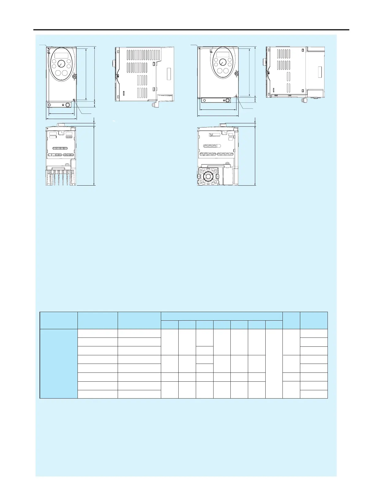
130
R2.5
15
121.5 (H1)
60 (W1)
D
8
72
Fig. A Fig. B
130
R2.5
13
121.5 (H1)
93 (W1)
φ5
D
8
105
Note 1: To make it easier to grasp the dimensions of
each inverter, dimensions common to all
inverters in these figures are shown with
numeric values but not with symbols.
Here are the meanings of the symbols used.
W: Width
H: Height
D: Depth
W1: Mounting dimension (horizontal)
H1: Mounting dimension (vertical)
H2: Height of EMC plate mounting area
D2: Height of frequency setting knob
φ5
Input voltage
3-phase 200V
0.2 HF3212-A20
120
0.9
0.4 HF3212-A40 72 130 60 121.5 15 A 0.9
0.75 HF3212-A75 130 1.1
1.5 HF3212-1A5
105 130
130 93 121.5 13
8 B
1.2
2.2 HF3212-2A2 150 1.3
3.7 HF3212-3A7 140 170 150 126 157 14 C 2.2
5.5 HF3212-5A5
180 220 170 160 210 12 D
4.8
7.5 HF3212-7A5 4.9
Applicable motor
(kW)
Inverter type
Dimensions (mm)
Drawing
Approx. weight
(kg)
W H D W1 H1 H2 D2
 Loading...