Do you have a question about the LDG AT-1000 Pro and is the answer not in the manual?
Critical safety warning regarding RF energy handling and internal component safety.
Crucial safety advice for antenna installation near power lines to prevent injury or death.
Emphasizes not operating with the cover removed due to lethal RF voltages and not exceeding specifications.
Describes connecting the AT-1000 Pro to the amplifier, antenna, and power source for initial operation.
Details continuous frequency range and transmit power capabilities for different modes.
Outlines tuning time, memory capacity, and load impedance tuning capabilities.
Provides dimensions, weight, and power input requirements for the AT-1000 Pro.
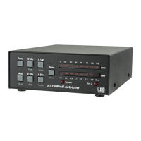
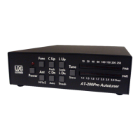
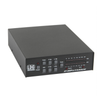
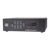
Describes the front panel layout with pushbuttons and the illuminated cross-needle meter.
Explains the primary function of each pushbutton on the front panel.
Details how to turn the unit on/off and enter FUNC mode.
Explains how the cross-needle meter displays power, SWR, and modes.
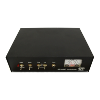
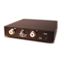
Describes connecting antenna feedlines to the SO-239 connectors.
Explains connecting the ground and the transmitter via coax jumper cable.
Details the connections for optional radio interface and the DC power input.
Advises on protecting the unit outdoors and using a balun for non-coax-fed antennas.
Guides on connecting transmitter, antenna, and DC power, emphasizing turning radio off first.
Recommends proper grounding and lightning arrestor installation for performance and safety.
Explains primary functions and secondary functions accessed via FUNC mode.
Details turning the unit on/off and entering FUNC mode.
Describes switching between automatic and semi-automatic tuning modes.
Covers antenna selection and switching meter scales between 100W and 1000W.
Details increasing capacitance and toggling between average/peak power display modes.
Describes decreasing capacitance.
Describes increasing inductance.
Describes decreasing inductance.
Explains selecting bypass/active mode, requesting tuning cycles, and manually storing settings.
Explains the memory and full tuning cycles and how the tuner learns settings.
Discusses exciter roll-back circuits and required power levels during tuning.
Describes how to use the fully automatic tuning mode.
Details the built-in relay protection against over-power or high SWR conditions.
Explains front panel LED blinking for over-range conditions on the 100W scale.
Details the procedure to initiate a memory tuning cycle.
Details the procedure to initiate a full tuning cycle.
Explains using buttons to manually adjust inductance and capacitance for optimal SWR.
Describes how to save manually tweaked tuning settings into memory.
Describes LED patterns indicating inability to determine frequency.
Explains LED patterns indicating relay protection activation due to SWR or power limits.
Details LED indications for no RF present, RF lost, or inability to find a good match.
Notes continuous tuning coverage beyond ham bands for MARS/CAP operation.
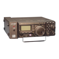
Explains integration with Icom transceivers using an optional interface cable.
Details integration with Yaesu transceivers using an optional interface cable.
Describes the pinout for the radio interface jack for custom connections.
Introduces concepts of impedance, resistance, capacitance, and inductance in RF circuits.
Explains characteristic impedance and the concept of a "matched" system.
Explains what a mismatch is and how reflected energy can damage transmitters.
Introduces the SWR formula and how SWR bridges work.
Describes how tuners cancel reactance and "fool" the transmitter.
Explains the switched L network, relays, and microprocessor control.
Details the Bruene circuit variation used for SWR sensing and power measurement.
Describes the microprocessor's algorithm for finding the best match, including fine tuning.
Advises using vacant frequencies to avoid interference during tuning operations.
Unit is maintenance-free; clean case with soft, damp cloth; avoid extremes.
Contact support via phone/email; find info online, manuals, and dealer links.
Covers defects for two years, transferable with sales receipt.
Send product for repair; estimate provided if needed; follow instructions.
Instructions for returning product, including repair form and address.
Encourages users to provide feedback on their product experience.
The LDG AT-1000 Pro is a 1000-watt automatic memory antenna tuner designed for amateur radio enthusiasts. It provides semi-automatic and fully automatic antenna tuning across the entire HF spectrum plus 6 meters, handling power levels up to 1000 watts (SSB). This tuner is capable of matching a wide range of antennas, including dipoles, verticals, Yagis, and virtually any coax-fed antenna, offering a greater impedance range than many other tuners, including those built into radios. An upgrade from LDG's previous AT-1000 kilowatt tuner, the Pro version now supports fully automatic tuning with frequency-based memories, making it suitable for high-power amplifier applications.
The AT-1000 Pro's operation is primarily controlled via its front panel, which features eight pushbutton switches and a 3-inch illuminated cross-needle meter. The "Power/Func" button serves to turn the unit on/off and to enter "FUNC" mode, which activates secondary functions for other buttons. A momentary press turns the unit on, while a three-second press and hold turns it off, placing it in a low-power sleep mode where relays are de-energized, the tuner is bypassed, and ANT 2 is selected.
The "Auto/Thresh" button toggles between fully automatic and semi-automatic tuning modes. In fully automatic mode, the tuner initiates a memory tuning cycle whenever the SWR exceeds a pre-set threshold. If the Auto LED is off, the tuner is in semi-automatic mode, requiring a manual press of the "Tune" button to start a tuning cycle. The SWR Threshold can be adjusted in FUNC mode by pressing "Auto/Thresh," with the cross-needle meter displaying the current threshold. Available thresholds include 1.5:1, 1.7:1, 2.0:1, 2.5:1, and 3.0:1.
The "Ant1/Scale" button selects between Antenna 1 and Antenna 2. When in FUNC mode, this button also allows selection of the meter scale, toggling between 0-100W and 0-1000W displays. The "C Up" and "C Dn" buttons manually increase or decrease capacitance, respectively, while "L Up" and "L Dn" control inductance. Holding these buttons down results in rapid adjustment. The "C Up/Peak" button also has a secondary function in FUNC mode, toggling between average and peak power readings on the cross-needle meter.
The "Tune/Store" button has three functions: toggling bypass/active mode, initiating a tuning cycle, and manually storing tuning settings. A momentary press toggles between bypass (all inductance and capacitance removed) and active mode (previous settings restored). To request a memory tuning cycle, press and hold "Tune/Store" until the Tune LED lights. For a full tuning cycle, continue holding until the Tune LED extinguishes again. In FUNC mode, pressing "Tune/Store" stores current inductor and capacitor settings to memory.
The AT-1000 Pro employs two tuning cycles: memory tuning and full tuning. Memory tuning quickly recalls previously stored settings for a given frequency, making it nearly instantaneous if a match is found. A full tuning cycle starts from scratch, systematically varying inductance and capacitance to find the best match. The tuner "learns" over time, saving successful settings for future recall. After a tuning cycle, the carrier is held for 1.5 seconds to allow SWR verification on both the tuner's meter and the transceiver's internal meter.
The tuner incorporates a built-in relay protection system, preventing tuning if input power exceeds 150 watts with SWR over 3:1, or 200 watts at any SWR, to avoid relay arcing. The cross-needle meter displays forward and reflected power, as well as SWR, with an accuracy of ±10% across the full scale. An over-range condition (more than 125 watts in 100W scale) is indicated by blinking front panel LEDs.
For fine-tuning, the AT-1000 Pro offers complete manual control over tuning parameters. Users can increment or decrement inductance and capacitance using the dedicated buttons. The tuner uses an L-network, and a relay allows switching the capacitance arm to either the transmitter or antenna side of the inductor bank, accommodating a broader range of antenna loads. To select settings for higher impedance antennas, press "C Up" and "L Up" simultaneously; for lower impedance, press "C Dn" and "L Dn" simultaneously. Manually adjusted settings can be stored in memory via FUNC mode.
The AT-1000 Pro provides continuous tuning coverage beyond ham bands, making it suitable for MARS/CAP operations. It offers integration with many Icom and Yaesu transceivers via optional interface cables, allowing tuning requests directly from the radio. The "Radio Interface" jack on the rear panel follows the Icom tuner interface format, featuring a "Start" input to initiate tuning and a "Key" output to request a carrier from the radio.
The tuner's internal design utilizes banks of fixed capacitors and inductors, switched by microprocessor-controlled latching relays. An SWR sensor, a variation of the Bruene circuit, provides real-time forward and reflected power levels to the microprocessor for SWR calculation. The microprocessor's algorithm minimizes adjustments, first finding a coarse match by stepping through inductors, then capacitors, and repeating the process with the high/low impedance relay energized if needed. A fine-tune routine then optimizes the SWR to the lowest possible value.
Maintenance for the AT-1000 Pro is minimal. Adhering to power limits is crucial. The outer case can be cleaned with a soft, damp cloth. As with any electronic device, protection from temperature extremes, water, impact, and static discharge is important. LDG strongly recommends using a properly installed, high-quality lightning arrestor on the antenna lead.
LDG provides a two-year transferable warranty against manufacturer defects. Product registration is not required; the original sales receipt serves as proof of purchase. The warranty does not cover damage from customer abuse, failure to heed specifications, or natural calamities like lightning. For out-of-warranty service, products can be sent to LDG for repair, with an estimate provided if requested. LDG encourages product feedback to improve future designs.
| Tuner Type | Automatic Antenna Tuner |
|---|---|
| Input Impedance | 50 Ohms |
| Output Impedance | 50 Ohms |
| Input Voltage | 13.8 VDC |
| Power Handling | 1000 Watts |
| Impedance Matching Range | Matches 10:1 or greater SWR |
| Current Consumption | 1.5A max |
| Dimensions | 3.5" |
| Control Interface | manual |
| Frequency Range | 1.8 to 54 MHz continuous coverage |