EasyManua.ls Logo

LDG Z11 - User Manual

LDG Z11
13 pages
Print Icon
To Next Page IconTo Next Page
Loading...
- 1 -
Introduction: The Z11 is a full featured QRP auto or semi automatic antenna tuner designed for
HF (1.8 to 30 MHz) transceivers using between 0.1 to 30 watts. The tuner uses a switched "L"
configuration with 256 capacitor, 256 inductor and Hi/Lo-Z settings to provide over one hundred and
thirty thousand tuning combinations. The tuning range is 0 to 2700 pF and 0 to 20 uH. The "L"
network works great with just about any coax fed antenna (dipole, vertical, beam, etc). Users with
long wires can install a balun between the tuner and the antenna. Tuning time is between 0.1 and
3.0 seconds with the average being about 1.5 seconds.
Latching relays are used to switch tuning components into and out of the tuning circuit. These
relays will hold the tuning configuration even if power is removed from the tuner. Once a tune has
been made the tuner enters a low power mode where it only draws 0.008 amps. Placing the tuner
into Standby can further reduce this power consumption, where it draws zero amps. During tuning,
the tuner may temporarily draw up to 0.4 amps. This current draw usually only last a second or two.
Three LEDs provide an indication of SWR while RF is present. Green indicates SWR of less than
1.5, Green/Yellow is 1.5-2.0, Yellow is 2.0-2.5, Yellow/Red is 2.5-3.0 and Red indicates more than
3.0. The fourth LED is a tuning indicator. It is lit only when the tuner is trying to find a match.
Operation: Turning on the unit with the front panel Power switch will initialize the microprocessor.
All four LEDs will flash once to indicate the power up process was initiated. Turning the unit off by
the front panel Power switch places the tuner into Standby. The tuning configuration is maintained
with the Power switch in either position.
Question and Answer IconNeed help?

Do you have a question about the LDG Z11 and is the answer not in the manual?

Summary

Performance and Support

Antenna Performance Results

Real-world tuning performance with various antennas like dipoles and inverted-Vees.

Building the Kit: Preparation and Winding

Toroid Winding Instructions

Detailed steps for winding inductors on T50-2 toroids.

Winding Chart

Reference chart for inductor winding specifications (uH, turns, inches).

Component Installation: Core Components

Installing Resistors and Crystal

Instructions for installing resistors (R1-21) and the 4.5 MHz crystal.

Component Installation: Switches and Front Panel

Chassis Assembly and Final Testing

Initial Power-Up

Applying power and checking for correct voltage and current draw.

Tuner Alignment Procedure

Step-by-step calibration process for REV, FWD, and REF test points.

Overview

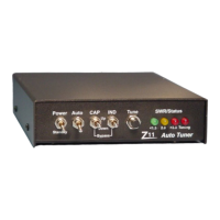
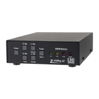
The Z11 is a QRP (low-power) automatic or semi-automatic antenna tuner designed for HF (High Frequency) transceivers operating between 1.8 and 30 MHz, with power outputs ranging from 0.1 to 30 watts. It utilizes a switched "L" configuration, offering a wide range of tuning combinations with 256 capacitor and 256 inductor settings, along with Hi/Lo-Z options. This results in over 130,000 possible tuning configurations. The tuning range for capacitance is 0 to 2700 pF, and for inductance, it is 0 to 20 uH. The "L" network is compatible with various coax-fed antennas such as dipoles, verticals, and beams. For users with long wire antennas, a balun can be installed between the tuner and the antenna for optimal performance. Tuning typically takes between 0.1 and 3.0 seconds, with an average tuning time of about 1.5 seconds.

Technical Specifications:

  • Frequency Range: 1.8 to 30 MHz
  • Power Handling: 0.1 to 30 watts
  • Tuning Configuration: Switched "L" network
  • Capacitor Settings: 256
  • Inductor Settings: 256
  • Impedance Options: Hi/Lo-Z
  • Total Tuning Combinations: Over 130,000
  • Capacitance Range: 0 to 2700 pF
  • Inductance Range: 0 to 20 uH
  • Average Tuning Time: 1.5 seconds (range: 0.1 to 3.0 seconds)
  • Power Consumption (Low Power Mode): 0.008 amps
  • Power Consumption (Standby): 0 amps
  • Power Consumption (During Tuning): Up to 0.4 amps (typically for 1-2 seconds)
  • DC Power Input: 11 to 15 volts DC (center pin positive), capable of supplying up to 0.4 amps for up to two seconds.
  • Portable Operation: Two rechargeable 9V batteries in series provide approximately 14V DC at 0.120 AHr. With a draw of 0.0002 AHr per tune, the unit can achieve about 500 tunes on a single charge.
  • SWR Tuning Range: Consistently tunes impedances from approximately 6 ohms to 850 ohms, corresponding to an SWR of about 10:1.
  • SWR Bandwidth (usable at 1.5 SWR without retuning): Averaged about 200 kHz (smaller at lower frequencies, e.g., 75 kHz on 80 meters; larger at higher frequencies, e.g., 400 kHz on 10 meters).

Usage Features:

The Z11 incorporates latching relays for switching tuning components. This design ensures that the tuning configuration is maintained even if power is removed from the tuner. After a successful tune, the tuner enters a low-power mode, drawing only 0.008 amps. Placing the tuner in Standby mode further reduces power consumption to zero amps. During active tuning, the unit may temporarily draw up to 0.4 amps, typically for a second or two.

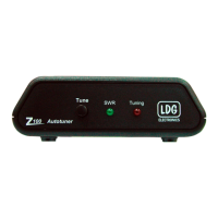
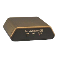
Three LEDs provide visual feedback on the SWR when RF is present:

  • Green: SWR less than 1.5
  • Green/Yellow: SWR between 1.5 and 2.0
  • Yellow: SWR between 2.0 and 2.5
  • Yellow/Red: SWR between 2.5 and 3.0
  • Red: SWR greater than 3.0

A fourth LED serves as a tuning indicator, illuminating only when the tuner is actively searching for a match.

Operation Modes:

  • Initialization: Turning on the unit via the front panel Power switch initiates the microprocessor. All four LEDs will flash once to confirm the power-up sequence.
  • Standby: Turning the unit off with the Power switch places it in Standby, preserving the current tuning configuration.
  • Auto Mode: Controlled by the Auto/Semi toggle switch. In this mode, the tuner automatically seeks an SWR match of 1.5 or better whenever the SWR rises above 3.0.
  • Semi Mode: Also controlled by the Auto/Semi toggle switch. In Semi mode, the tuner will only seek a match when the Tune push button is pressed.
  • RF Power Requirement: Both Auto and Semi modes require more than 0.1 watts of RF power to tune properly. If the Tune button is pressed with insufficient RF power, all four front LEDs will flash once to indicate the issue.
  • Fine Tuning: The Capacitor Up/Down and Inductor Up/Down switches allow for manual fine-tuning of the inductors and capacitors in both Auto and Semi modes. Pressing an "Up" switch increments the tuning section until its maximum range is reached, at which point all four LEDs will flash. Conversely, pressing a "Down" switch decrements the tuning section until its minimum range is reached, also indicated by all four LEDs flashing.
  • Hi/Lo-Z Control:
    • Pressing the Tune and Ind Up push buttons simultaneously moves the Hi/Lo-Z relay to the Hi-Z position. The red Tuning LED will flash to confirm this change.
    • Pressing the Tune and Ind Down push buttons simultaneously moves the Hi/Lo-Z relay to the Lo-Z position. The green 1.5 SWR LED will flash to confirm this change.
  • Processor Reset/Bypass: Pressing both Down switches simultaneously resets the processor and places all relays in a bypass position.
  • General Tuning: For most situations, simply transmit a continuous carrier and press the tune button; the tuner will automatically find the best match and stop.
  • Interrupted Tuning: If power (RF or +12V) is removed during a tuning cycle, the LEDs will turn off, and tuning will cease. The resulting tune will be undetermined and may not be a match.

Construction and Assembly (Kit Version):

The Z11 is available as a kit requiring assembly. Builders should familiarize themselves with all components and their placement. The assembly involves over 100 parts and 450 solder connections.

  • Inductor Winding: The first step is winding the inductors on nine T50-2 toroids (red, approximately one inch in diameter). Eight inductors are wound using #24 gauge wire. L8 consists of two toroids glued together. L1-L4 are wound in one direction, and L5-L8 in the opposite. The PC board has offset solder pads to guide correct winding direction. Wire ends should be trimmed to about 1.5 inches and insulation scraped off before soldering. A winding chart provides specific lengths of wire and number of turns for each inductor (L1-L8). One turn is counted each time the wire passes through the center of the toroid.
  • Transformer Winding (T1): T1, a small black toroid (under 0.5 inches in diameter), is wound with 10 turns using red and green #28 gauge wire in a bifilar fashion (two lengths wound simultaneously). The winding direction is crucial.
  • PC Board Assembly: Components are installed and soldered in order of height, from shortest to tallest, guided by the silk-screen layout on the PC board.
    • Resistors: R1, R11-21 (1/8 watt, values checked with ohmmeter).
    • Diodes: 1N4148 (D1, 2, 4-9) and 1N4001 (D3), noting band polarity.
    • SIP Resistor: 10K 10 Pin SIP resistor (RSIP1), noting pin 1 orientation.
    • T1 Installation: T1 lies flat against the PC board, with #18 wire from the SO-239 passing through its center. Silicon RTV or hot glue can be used to secure it after testing.
    • Monolithic Capacitors: .01uf (C3-8, 10, 12-13, 23-24, 35).
    • SIP Capacitors: .01uf 50v 8 pin (C11, 17, 19-22), noting pin 1 marking.
    • Voltage Regulator: 78L05 (U4), noting orientation.
    • Transistors: 2N3904 (Q1-2), noting orientation.
    • Variable Resistors: 100K pots (R22-23).
    • Trimmer Capacitor: C1, noting common pins.
    • Sockets: U1 (52 Pin PLCC), U2 (44 Pin PLCC), U3 (8 Pin DIP), noting flattened corners/notches for orientation. ICs (68HC11, UCNQ5818, LN311) are installed later.
    • Ceramic Capacitors: Various values (C2, 14-16, 25-34).
    • Relays: K1-K17, carefully installed to avoid bending pins.
    • Crystal: 4.5 MHz (X1).
    • Electrolytic Capacitors: C9 (10 uf radial) and C18 (1 uf radial), noting polarity.
    • Header: 14 Pin (J3), soldering shorter ends to PC board.
    • Inductors L1-L8: Installed on PC board, ensuring insulation is scraped off and windings touch the board. RTV or hot glue is recommended for L1-L4, especially for mobile applications.
  • Wiring Connections:
    • A 2-inch length of #24 wire connects T1 to one SO-239 (transmitter).
    • A 1.5-inch length of #24 wire connects the PC board (next to L8) to the other SO-239 (antenna).
    • Leftover #24 gauge wire pieces (1.5 inches for J1, 1.5 inches for J2) are used with terminal lugs to connect to the PC board at J1 & J2 for grounding.
  • Front Panel Assembly:
    • Header: 14 pin header with 0.1-inch spacing installed on the white silk-screened side of the front panel PC board.
    • Resistors: R1 & R2 (470 ohm 1/8 watt) and R3 & R4 (100 ohm 1/8 watt) installed on the opposite side of the header.
    • Chassis Preparation: Unwrap the enclosure, attach rubber feet, ensuring they don't cover mounting holes.
    • Switches:
      • 2 SPST toggle switches (S1 & S2) for Power and Auto positions.
      • 2 SPDT momentary switches (S3 & S4) for CAP and IND positions.
      • 1 push-button switch (S5) for Tune position.
      • Switches are installed in the chassis, nuts and washers replaced, and solder terminals aligned. They should not be tightened until LEDs are aligned.
    • LEDs: LED1 (Green), LED2 (Yellow), LED3 & LED4 (Red) are placed in the front panel board, with the ground leg (notched plastic) down. Not soldered yet.
    • Front Panel PC Board Installation: The PC board is gently pushed onto the switch terminals, with the side without silk screen facing the terminals. LEDs slide into chassis holes in the order: Tune Switch, Green, Yellow, Red, Red. Once alignment is checked, switches are soldered to the PC board, nuts tightened, LEDs slid into chassis, and their legs soldered and clipped.
    • Power Jack: Panel mount power jack installed, middle pin facing SO-239 holes. Pin 1 towards top, Pin 3 towards bottom. Ground wire from J1 connects to Pin 2 of the power jack.
  • Final PC Board Mounting: The Z11 PC board is mounted in the chassis using four screws, nylon spacers, washers, and nuts. Screws are inserted from the bottom, nylon spacers placed, then the PC board (toroids towards back, microprocessor sockets/header towards front), followed by lock washers and nuts. Tighten gently.
  • SO-239s: Installed in back panel holes, terminal lugs attached to top mounting screws.
  • IC Installation: U1 (68HC11) and U2 (UNCQ5818) are carefully pressed into their sockets, matching flattened corners/notches.
  • Ribbon Cable: Connect pin 1 of J3 to pin 1 on the 2x7 header on the front panel.
  • Power Jack Wiring: Insulated wire connects J4 – Pin 2 (round) to Pin 1 (square) of the panel mount power jack.

Calibration:

  1. Power On: Apply 11-14V DC to the power input (center pin positive). Turn on the unit; all LEDs should flash simultaneously.
  2. Voltage Check: Verify +5.0V on the output of U2 (78L05), which is the pin closest to the oscillator.
  3. Current Draw: Current draw should be around 8 mA (5-10 mA is acceptable).
  4. R22/R23 Adjustment: Set R23 (REV) and R22 (FWD) to the center position.
  5. C1 Tuning (REV): Connect transmitter and antenna (or dummy load) to proper ports. With a voltmeter on test point REV, apply about 5 watts, and tune C1 for minimum DC voltage (ideally 0.0V, 0.1V is acceptable). A 50-ohm load (dummy or resonant antenna) is essential for this alignment.
  6. R22 Adjustment (FWD): With 5 watts and voltmeter on test point FWD, adjust R22 for 2.5V (2.0-2.5V is acceptable). This is a coarse adjustment.
  7. R23 Adjustment (REF): Reverse coax cables for transmitter and antenna ports. With 5 watts and voltmeter on test point REF, adjust R23 for 2.5V (2.0-2.5V is acceptable). This is a coarse adjustment.
  8. Low Power Adjustment: If 5 watts are unavailable, use 2-3 watts and adjust for 1.5V. Once calibrated, the tuner is ready for use.

Maintenance Features:

  • Repair Service: LDG Electronics offers a flat-fee repair service for the Z11, costing $50 plus parts. Most resistors and capacitors are included in this fee. Specific part costs: 68HC11 chip ($20), relays ($5 each), 78L05 ($1).
  • Repair Limitations: LDG will not repair units soldered with acid core and reserves the right to refuse repair for excessive problems or damage due to construction.
  • Return Authorization: Units must have return authorization before being sent for repair.
  • Prepaid Shipping: All units sent for repair must be prepaid (check, money order, or credit card, unless other arrangements are made).
  • Packaging: Units should be carefully packaged, as the original packaging will be used for return shipping.
  • Repair Information: Include a detailed description of the problem, name, address, and phone number. Repairs typically take 2-4 weeks.
  • Upgrades: Users with ideas for software or hardware improvements can submit descriptions. If an idea is used, a free upgrade will be provided. Future upgrades will be available for about $10 with a 68HC11 chip trade-in. Kit purchasers will be notified via the LDG Newsletter. Non-kit purchasers can be added to the mailing list by mail, fax, or email.
  • Feedback: Users are encouraged to provide feedback (card, letter, or email) on their experience with the Z11. Photographs of the Z11 in use are also welcome and may be featured in the LDG Newsletter or on their website (www.ldgelectronics.com).
  • Technical Support: Available by phone at 410-586-2177 (most days, 8 am to 9 pm Eastern Standard Time), FAX at 410-586-8475, and email (ldg@ldgelectronics.com) daily.

LDG Z11 Specifications

General IconGeneral
BrandLDG
ModelZ11
CategoryTuner
LanguageEnglish

Related product manuals