Do you have a question about the LDG IT-100 and is the answer not in the manual?
Quick start instructions for immediate operation and initial setup.
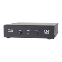
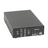
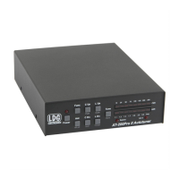
Details the IT-100's front panel controls, buttons, and LED indicators.
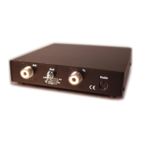
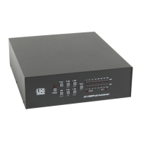
Describes the connectors and ports located on the rear of the IT-100 unit.
Lists the Icom transceiver models supported by the IT-100.
Provides instructions for connecting the tuner to the transceiver and antenna system.
Explains how the IT-100 powers on and off automatically with the transceiver.
Details the memory and full tuning cycles for achieving antenna matches.
How to initiate tuning using the transceiver's dedicated TUNER/CALL button.
How to control tuning functions directly from the IT-100's front panel button.
Step-by-step guide to start a quick tune using previously stored frequency memory.
How to initiate a complete re-tuning process for optimal antenna matching.
Explains the meaning of different LED states during operation and tuning.
Provides tips for using the tuner, including status, installation, and band changes.
Discusses suitability and requirements for mobile operation.
Fundamental concepts of impedance in RF circuits and their components.
How impedance applies to transmitters, transmission lines, and antennas.
Explains Standing Wave Ratio (SWR) and how it is measured.
How a tuner corrects impedance mismatches and protects transmitter output circuits.
Details the internal components and switched L-network design of the IT-100.
Explains the SWR sensing circuit and the operation of the tuner's relays.
Describes the microprocessor's method for finding the optimal antenna match.
| Type | Automatic Antenna Tuner |
|---|---|
| Frequency Range | 1.8 to 54 MHz |
| Input Impedance | 50 Ohms |
| Output Impedance | 50 Ohms |
| Weight | 1.5 lbs |
| SWR Range | 1:1 to 3:1 |
| Current Consumption | 300 mA |
| Impedance Range | 16 to 150 Ohms |