54
MOUNTING AND WIRING OF THE DISPLAY UNIT
Always disconnect power from the display unit before disconnecting the valve
cable. This allows avoiding possible power surges, which could damage the
electronic components of the unit.
1. The sensor of the valve unit is connected to the connector of the valve coil and
the “Valve” connector of the display.
2. There is a channel with a white nylon screw in the black sensor unit. The sensor
cable is installed fully inserted to the bottom of this channel and fastened
loosely with the screw, ensuring however that the sensor does not get detached
by accident. The other end of the sensor cable is connected to the connector
“Sensor”.
3. The display is fastened to the wall with screws. The drilling template shows the
correct distance between the holes.
4. The power adaptor is connected to the socket and the connector “Power” of the
display.
Should longer cables be required the installer may need to install custom cabling.
AFTER INSTALLATION
CHECK THAT ...
• The display does not register any flow when water supply is turned off
• The flow indicator’s blue light is on, when water is running continously
• The blue LED goes out a moment after the tap is closed
• The flow indicator’s blue light flashes a short while after water has been running
for a short period of time or if water is continuously dripping.
• To carry out the functionality test set the system into the Away and then run
water until the flow is registered. After a moment the valve unit shuts off and
the red alarm light comes on. If the audio alarm is activated you will hear the
alarm sound.
• Warnings and alarms are reset with the Reset button. A short push turns off the
alarm sounds, while holding the button resets the respective alarm causing the
solenoid valve to open, and the red alarm light goes out.
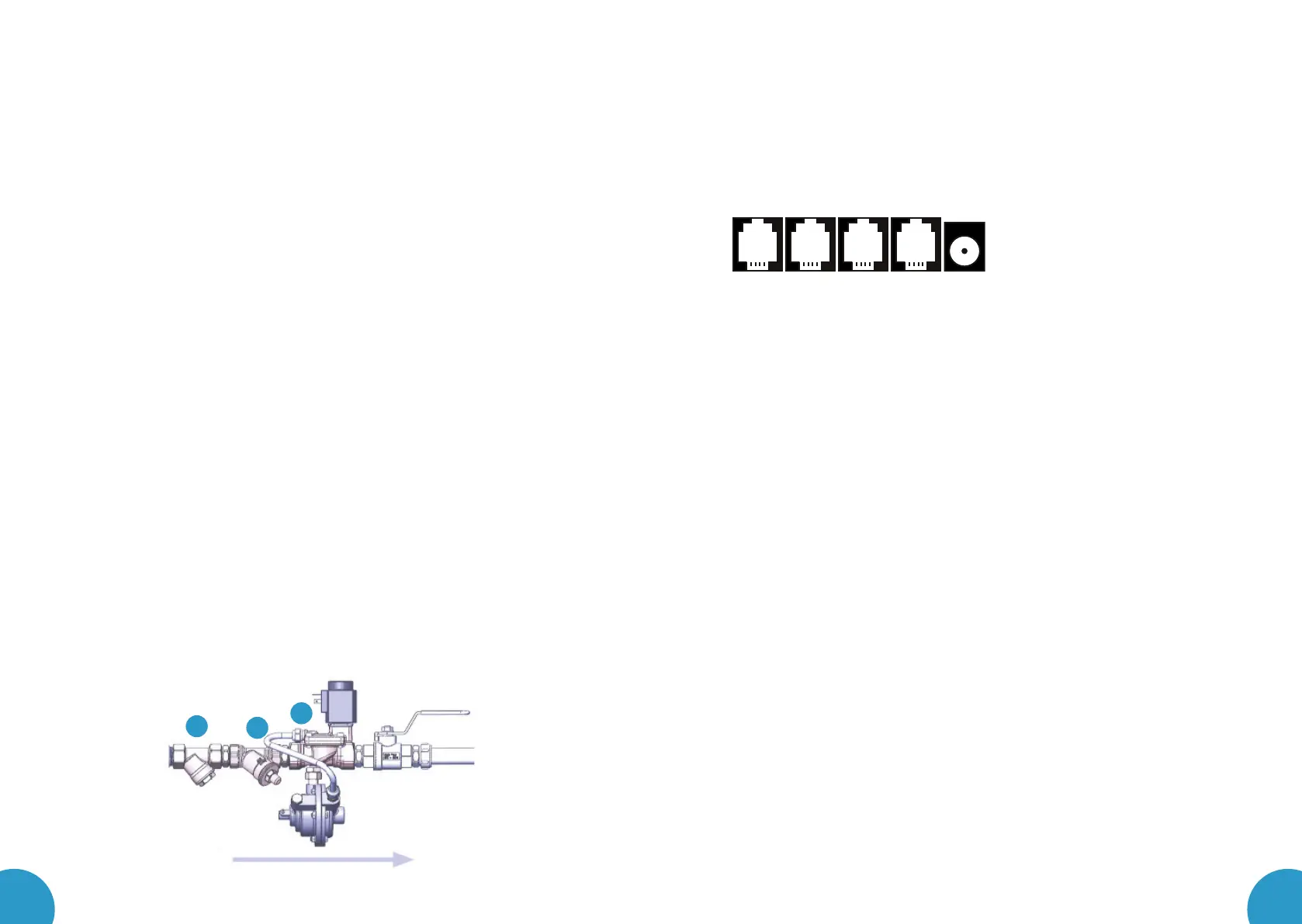
AUX outAUX in Sensor Valve Power
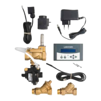
INSTALLATION OF PRODUCT
INSTALLATION OF THE VALVE UNIT
1. First close the shutoff valve of the water network.
2. Before installing the valve unit into any new water pipes, the pipes need to be
flushed carefully, until no particles can be observed in the flushing water.
3. Any accessories supplied with the product package are manufactured of brass
approved for pressurized tap water, and are installed in copper pipes. In order
to avoid corrosion caused by galvanic current, never use any parts or mate-
rials, which are galvanized, zinc-plated or made of black steel for mounting
purposes.
4. The dirt filter, the back flow check valve, and the Leakomatic valve unit are
mounted in order as illustrated below after the water meter, or as close to it as
possible. The arrow on the solenoid valve shows the direction of the flow of water.
Be extremely careful when cutting any pipes for mounting purposes, and make sure
that no thread seal tape or flax fibres are left inside the pipes, which could be car-
ried by water into the valve unit and prevent the Leakomatic sensor from working.
5. The valve unit can be mounted into either a horizontal or a vertical pipe.
6. The white plastic tube can carefully be folded away or temporarily be detached
from the solenoid valve when mounting the back flow check valve.
7. If possible, mount the valve unit such that the coil is facing up, in order to pre-
vent particles from getting into the coil shaft.
8. The valve unit should be mounted so that it is not affected by any lateral or
longitudinal compression, torsion or traction forces.
9. After the valve unit is in place, fasten the coil to the coil shaft so that you can
hear a clear “click”, when the coil locks into place.
10. Open the shutoff valve of the water supply network.
11. Inspect the installation ensuring water tightness of the assembly.
We recommend installing a ball valve after the valve unit to facilitate subsequent mainte-
nance operations.
1
8
7
 Loading...