steady. Returning the switch to NORM extin-
guishes the lights.
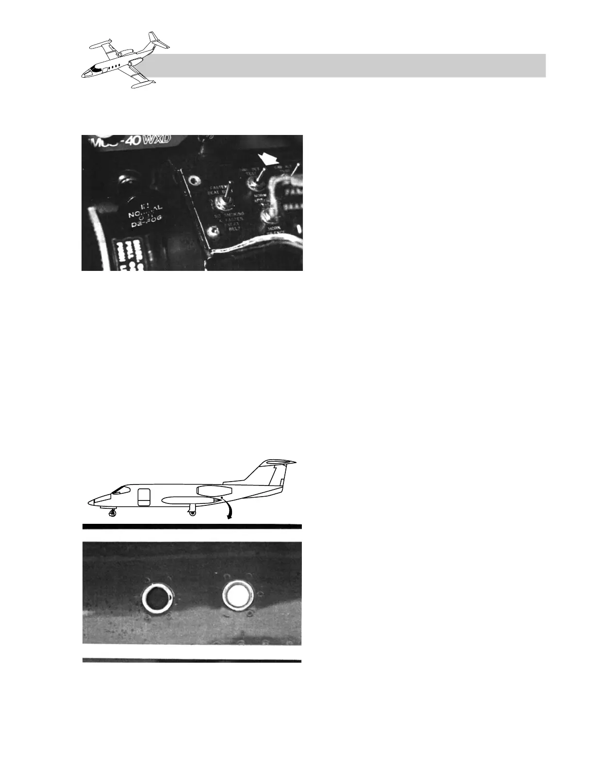
EXTERIOR EXTINGUISHER
DISCHARGE INDICATORS
Two colored disc indicators are flush-mounted
in the side of the fuselage below the left en-
gine pylon (Figure 8-3). The red disc covers
the thermal discharge port. It will be ruptured
if one or both thermal relief valves have re-
leased bottle pressure. The yellow disc will be
ruptured if either bottle is discharged by de-
pressing an illuminated ARMED light. The
integrity of the two discs is checked during the
external preflight inspection.
ENGINE FIRE
EXTINGUISHING
EXTINGUISHER CONTAINERS
Two spherical extinguishing agent contain-
ers are located in the tailcone area. Both con-
tainers use common plumbing to both engine
cowlings via shuttle valves, providing the air-
plane with a two-shot system. The chemical
agent in the containers, monobromotrifluo-
romethane (CF
3
Br), is not corrosive, and its
discharge will not necessitate cleaning of the
engine and cowl areas.
The containers are plumbed to each engine
cowling to provide the airplane with a two-shot
system. The containers will fully discharge in
one to two seconds. A pressure gage mounted
on each container indicates the charge of the
container. A thermal relief valve on each con-
tainer is plumbed to a thermal (red) discharge
indicator to relieve bottle pressure when bot-
tle temperature reaches 217ºF.
Access to the fire-extinguishing container is
through the tailcone door.
OPERATION
When a FIRE light illuminates (or flashes), it
indicates a fire or overheat condition in the re-
spective engine cowling. The pilot should first
place the thrust lever of the affected engine to
CUT OFF, then proceed with the AFM proce-
dures. A brief description of system operation
is as follows:
Airplanes With Glareshield
Warning Lights
Lifting the guard and depressing the red FIRE
warning light applies 28 VDC to close the hy-
draulic and fuel shutoff valves, and on airplanes
SNs 24-350 and subsequent and 25-227 and
subsequent, it closes the associated bleed-air
8-3
FOR TRAINING PURPOSES ONLY