GENERATORS
Two engine-driven starter-generators, one on
each engine, provide the primary source of
airplane DC power. Each generator is rated at
30 volts DC, 400 amperes. Cooling air is routed
from a scoop on the engine nacelle to the as-
sociated generator. During normal operation,
both generators operate in parallel through
the voltage regulators located in the tailcone.
As long as the battery switch is in ON, either
generator charges both batteries through the
associated 275-ampere current limiter. The
generators supply DC power to all DC equip-
ment installed on the airplane.
The generator control panel contains relays for
the batteries, starters, GPU overvoltage con-
trol, generator overvoltage control, and an
equalizer circuit for load sharing.
Voltage Regulators
SNs 23-003 through 24-189, and
SNs 25-003 through 25-029
Two Bendix carbon pile voltage regulators
are installed in the tail compartment on top of
the engine beam. Each unit consists of a car-
bon pile regulator, a resistor, a rheostat assem-
bly, and a voltage regulator base. The regulator
is set to maintain voltage at 28.5 VDC.
SNs 24-190 through 24-229, and
SNs 25-003 through 25-064
Two Phoenix Aerospace solid-state voltage
regulators are installed in the tail compart-
ment on the left side of the engine beam or elec-
trical equipment tray. The regulator maintains
a constant output voltage of 29.0 VDC under
varying engine speeds and load conditions.
The voltage regulator is factory adjusted, and
no regulator adjustment is allowed.
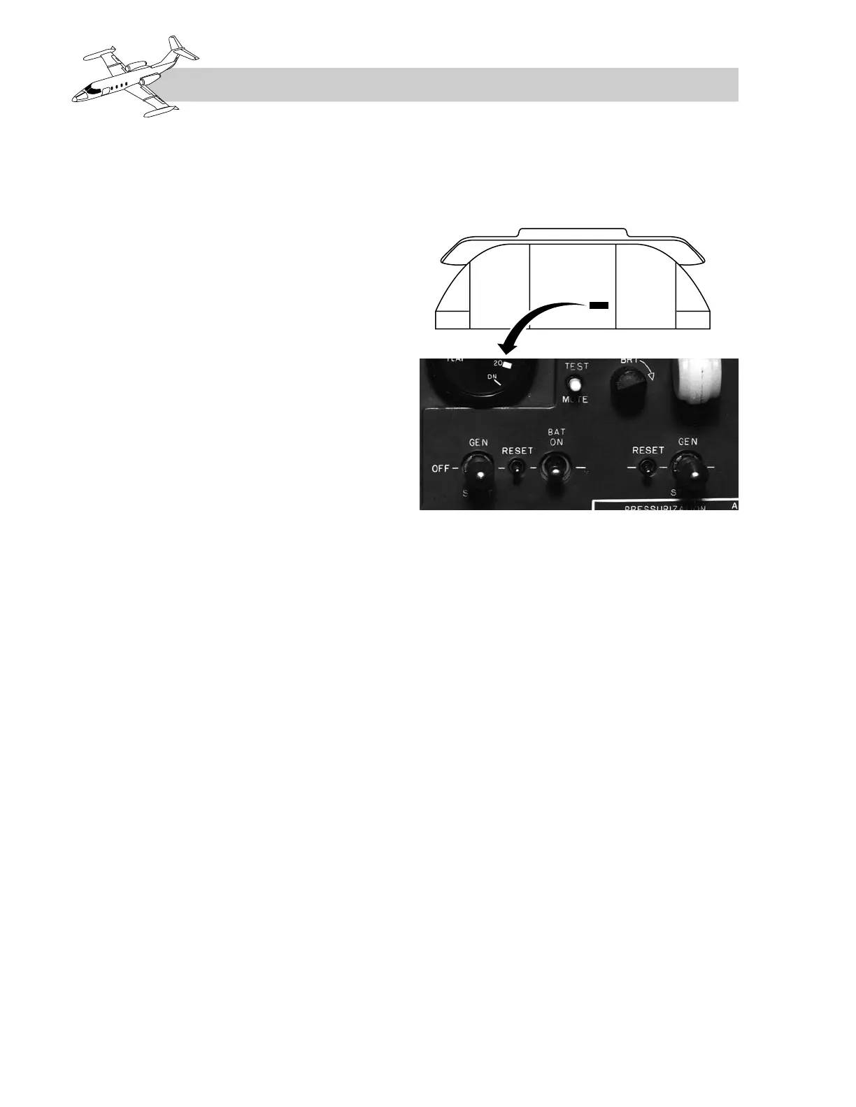
Controls
Two starter-generator switches (Figure 2A-4)
are installed on the switch panel. Each three-
position switch is marked “GEN–OFF–START.”
Moving the starter-generator switch to GEN
allows the generator relays to energize and
complete three circuits: a circuit for 28 VDC
to the voltage regulator, a circuit for power to
the Freon system compressor motor, and a cir-
cuit for the voltage regulator equalizer bus.
When placed to START position, the respec-
tive fuel motive flow control valve closes, the
standby fuel pump turns on, and the engine ig-
nition system arms. After the motive flow con-
trol valve closes, a circuit is completed to
energize the start relays. With the start relays
energized, battery power is applied to the
starter winding of the starter-generator.
On SNs 23-003 through 23-009 (without jet
pumps), there are no motive flow valves and
the pilot must turn on the main fuel pumps. On
airplanes through SN 23-009, the pilot must
also turn on the individual ignition switches.
Reverse Current Devices
Reverse Current Cutout Relays—
SNs 23-003 through 24B-189, and
SNs 25-003 through 25-029
Undervoltage, reverse current, reverse polar-
ity, and differential protection in each gener-
ator are provided by the reverse current cutout
relay. The relays are located on the generator
control panel in the tail compartment.
2A-4
FOR TRAINING PURPOSES ONLY