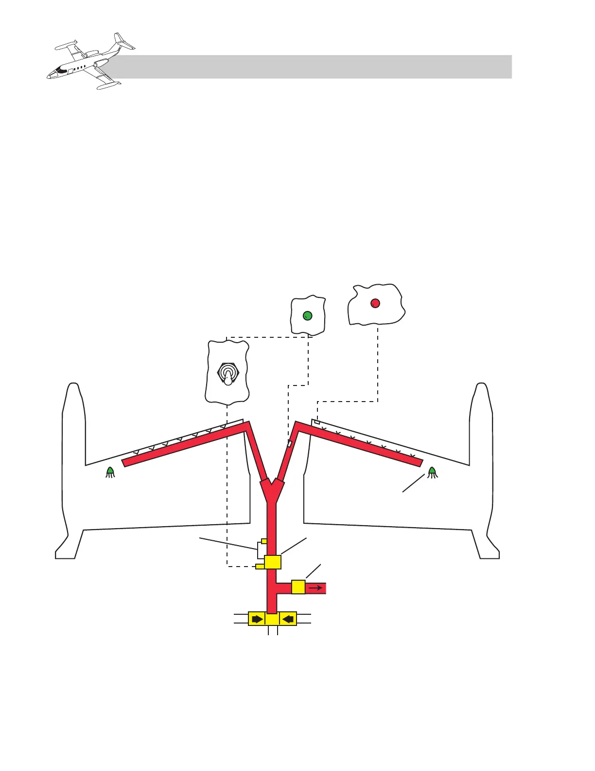
the leading edge (Figure 10A-10). The air is
then exhausted overboard through a scupper
drain on the bottom of the leading edge near
the tip tanks.
The control switch is usually located on the
pilot’s subpanel. The ON–OFF switch con-
trols electrical power to the wing regulator
valve located in the tail compartment.
The wing regulator valve is electrically con-
trolled and pneumatically operated. These air-
planes have one of two kinds of regulator
valves installed. The earlier kind is a Janitrol
valve which is electrically closed and fails to
the open position. The later kind is a Whittaker
valve which is electrically energized open and
fails to the closed position. Either valve reg-
ulates pressure to the wing ducts at 8 to 20 psi.
A green WING HEAT light illuminates when
the duct temperature reaches 215ºF. A red
WING OVERHEAT light illuminates when
the leading-edge structure temperature reaches
215ºF. Do not operate the system with the red
light illuminated.
10A-10
FOR TRAINING PURPOSES ONLY