GLARESHIELD
WARNING LIGHTS
The red and amber lights illuminate when a
malfunction is detected in the associated
system and remain illuminated until the
malfunction is cleared. The green lights illu-
minate to indicate that the associated system
is in operation.
TEST FUNCTION
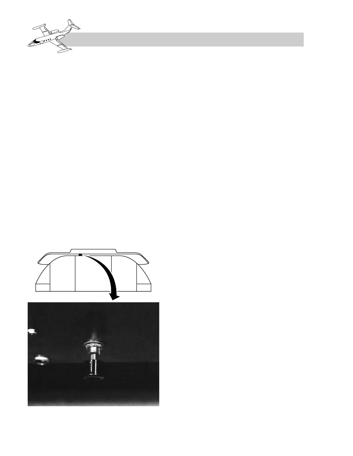
Depressing the test switch under the
glareshield (Figure 4-1) causes the following
lights to illuminate:
• All glareshield warning lights
• Shutoff valve lights
•Fire warning and fire extinguisher armed
lights
• Decision height lights
• Antiskid generator lights (Model 25
series airplanes)
• Air ignition lights
• All fuel panel lights
• Pitot heat indicator lights (if installed)
• T/O TRIM and OVSPD lights (if in-
stalled)
•LOW OIL, LOW HYD, and FUEL
XFLO (if installed)
INTENSITY CONTROL
The intensity of the landing gear warning
lights and the flight director annunciator lights
is dimmed when the navigation lights switch
is turned on. The gear lights are also con-
trolled by a rheostat on the landing gear panel.
Photoelectric cells, inboard of each FIRE
switch, automatically dim the lights on the
glareshield to a level corresponding to exist-
ing light conditions in the cockpit or to a min-
imum preset level for a totally dark cockpit.
On some airplanes there is also a rheostat
under the left side of the glareshield that con-
trols the intensity of the warning lights above
or below that of the photo cell value.
BULB CHANGE
Individual lights may be “popped out” ap-
proximately 1/4 inch by depressing and re-
leasing. The light may then be removed by
pulling out to replace either of the two bulbs
in each light. In the extended position (popped
out), the light is inoperative.
ILLUMINATION CAUSES
The lights associated with the glareshield warn-
ing system, their legends, colors, and causes
for illumination are shown in Table 4-1.
NOTE
Some lights are optional, and arrange-
ments may vary between airplanes.
4-2
FOR TRAINING PURPOSES ONLY