Flow Control Valve
The flow control valve admits air from the
bleed-air manifold and routes it to the heat ex-
changer for temperature control. The two
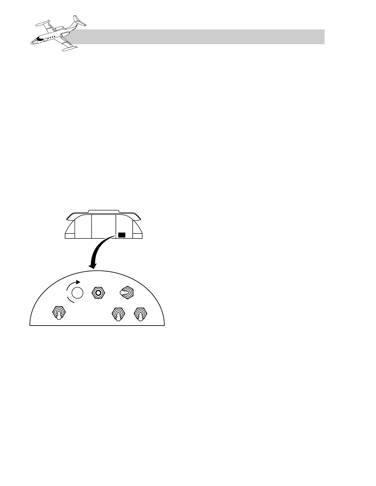
switches which control the valve are labeled
“AIR BLEED” and “NORM–MAX” (Figure
11-11). On models 23, 24, and 24B, the AIR
BLEED switch, when in ON, allows bleed air
to flow through the flow control valve, through
the heat exchanger to the venturi, and into the
cabin through the distribution ducts. The ven-
turi senses differential pressure which is sent
back to the flow control valve and modulates
the airflow in order to compensate for engine
power changes. The NORM–MAX airflow
switch, when positioned to MAX, opens the
flow control valve full open, allowing maxi-
mum airflow into the cabin.
Figure 11-11. AIR BLEED and NORM–
MAX Switches
Damper Valve
The damper valve is located just above the heat
exchanger in the ram-air inlet. The purpose of
the damper valve is to regulate the amount of
ram air passing through the ram-air scoops
across the heat exchanger and overboard, thereby
controlling the temperature of the bleed air for
cabin heating. The damper valve is operated by
the AUTO or MAN cabin heat control in the
cockpit. This valve requires approximately 27
seconds to travel from fully closed to fully open.
Heat Exchanger
The heat exchanger is a high-effectiveness,
two-pass crosscounterflow plate fin unit. High-
pressure bleed air is ducted into the heat
exchanger and routed through the core in cross-
counterflow directions. Ram air is routed over
the core channels and overboard just aft of
the tailcone access door. This results in a sub-
stantial reduction of bleed-air temperature.
Ram-Air Ventilation
In the event that the aircraft is unpressurized
in flight, air for circulation and ventilation of
the cabin and cockpit areas is provided by ram
air ducted into the conditioned bleed-air
distribution system.
During the normal operation, a one-way check
valve in the connecting ram-air duct prevents
loss of conditioned pressurization bleed air
through the ram-air plenum exhaust port.
Cabin and Cockpit
Air Distribution
Conditioned airflow distribution to the cabin
and cockpit areas is essentially the same for all
aircraft (see Figure 11-1). The conditioned air
is routed from the tailcone into the cabin area
through two ducts, one on each side of the
cabin. The left duct ends at the entry door, and
the right duct continues forward to the cockpit.
A footwarmer diffuser, located below the
instrument panel just forward of the center
pedestal, directs continuous conditioned air
along the center floor. Two piccolo tubes
(SNs 24-165 and subsequent and all model
25s), installed vertically on each side of the
windshield center support structure, direct a
continuous flow of conditioned air across the
forward section of each pilot’s windshield for
interior windshield defogging.
Temperature Control
Cabin temperature control is accomplished by
conditioning the engine bleed air, which is also
used for cabin pressurization. The cabin heat-
ing system can be controlled both manually
11-12
FOR TRAINING PURPOSES ONLY