and automatically. In both modes, the desired
temperature is maintained by varying the
amount of external ram air that is allowed to
flow through the air-to-air heat exchanger by
the use of a damper valve located in the ram-
air inlet duct. In the automatic mode, the damper
valve is controlled by the amount of signal
difference between the temperature selector
and the cabin temperature sensing elements.
Rapid temperature fluctuations are prevented
by a duct temperature sensor in the supply duct,
and a high-temperature limit switch prevents the
duct air temperature from exceeding safe limits.
In the manual mode, the position of the damper
valve is controlled directly by the pilot using
the HOT–COLD switch.
AUXILIARY
AIR-CONDITIONING
SYSTEMS
GENERAL
Supplemental cooling and heating are pro-
vided by a Freon refrigeration system and an
optional electric heating system. A cabin
blower distributes the conditioned air through-
out the interior. Beginning with SNs 24-204 and
25-040, a cockpit cooling fan is provided for
increased air circulation in the cockpit area. The
cabin blower and cockpit fan may be used
simply to recirculate air within the cabin and
cockpit areas or, by using the auxiliary cooler
or heater, to cool or to heat the recirculated air.
A ground power unit or an engine-driven
generator must be used to operate either the
cooling or heating systems on the ground.
DISTRIBUTION SYSTEM
The heart of the distribution system is the evap-
orator and blower assembly, installed in the cab-
inet behind the pilot’s seat on SNs 23-003 through
24-129 (Figure 11-12). On SNs 24-130 through
-203 and 25-003 through -039, the evaporator
with a single duct and the blower are installed
on the ceiling above the baggage compartment
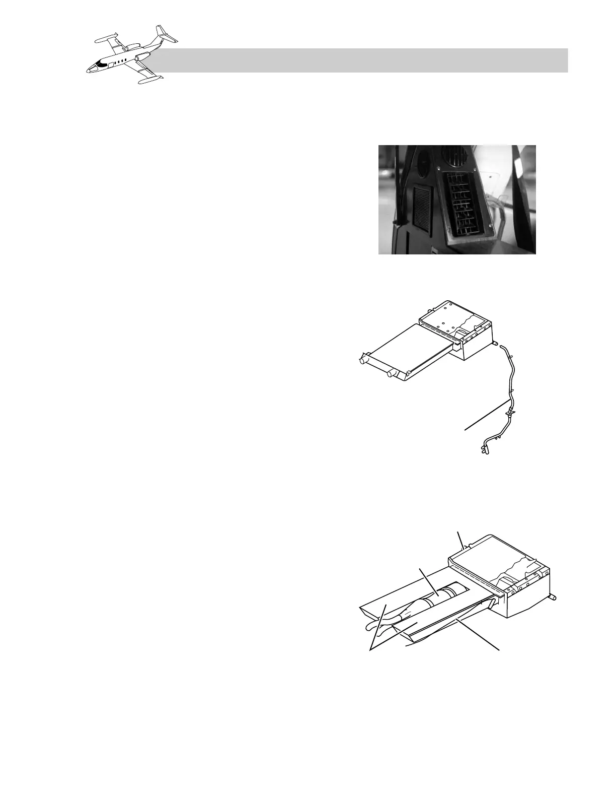
(Figure 11-13). On SNs 24-204 and subsequent
and 25-040 and subsequent, a dual duct and
blower are installed with a cockpit cooling fan
mounted between the ducts (Figure 11-14).
11-13
FOR TRAINING PURPOSES ONLY